
Split type ion source extraction electrode system

A technology for extracting electrodes and ion sources, used in circuits, discharge tubes, electrical components, etc., can solve the problems of thermal deformation and displacement of the electrode system, affecting the extracted beam current and beam quality, and difficulty in adapting to various beam currents. The effect of saving equipment investment and stable and reliable structure

Inactive Publication Date: 2012-02-08
BEIJING ZHONGKEXIN ELECTRONICS EQUIP
View PDF5 Cites 6 Cited by
  • Summary
  • Abstract
  • Description
  • Claims
  • Application Information

AI Technical Summary

Problems solved by technology

[0004] The present invention is aimed at the problem that the lead-out electrode system is prone to thermal deformation and displacement in the existing ion implanter technology, which causes the lead-out electrode to be misaligned, and the accelerating electrode seam is affected by ion beam sputtering, which causes the change of electrode structure parameters and affects the lead-out beam current. and beam quality, as well as a series of problems that a single extraction electrode is difficult to adapt to a variety of beam currents, a new structure ion source extraction electrode system is adopted. The above-mentioned problems of the extraction electrode system in the prior art meet the high reliability and high standard requirements of ion implanters, and one electrode can be applied to various beam currents

Method used


Image

  • Split type ion source extraction electrode system
  • Split type ion source extraction electrode system
  • Split type ion source extraction electrode system

Examples


Embodiment Construction

[0029] The present invention will be further introduced below with reference to the specific embodiments of the accompanying drawings. It should be understood that these descriptions are illustrative and the present invention is not limited thereto. The scope of the present invention is limited only by the scope of the appended claims.

[0030] first reference Image 6 , to introduce the arrangement and working principle of the key components of the ion implanter.

[0031] Such as Image 6 As shown, the ion source extraction electrode (not shown) extracts the ion beam generated in the ion source. In order to select the desired ion species from the total ion beam, so as to ensure the provision of ion species with a certain charge and mass number, such as boron (B), phosphorus (P), arsenic (As), argon (Ar), the ion beam Passes through a specialized ion sorting component - the mass analyzer. Then the ion beam passes through two sets of magnetic quadrupole lenses, which strong...


PUM


Abstract

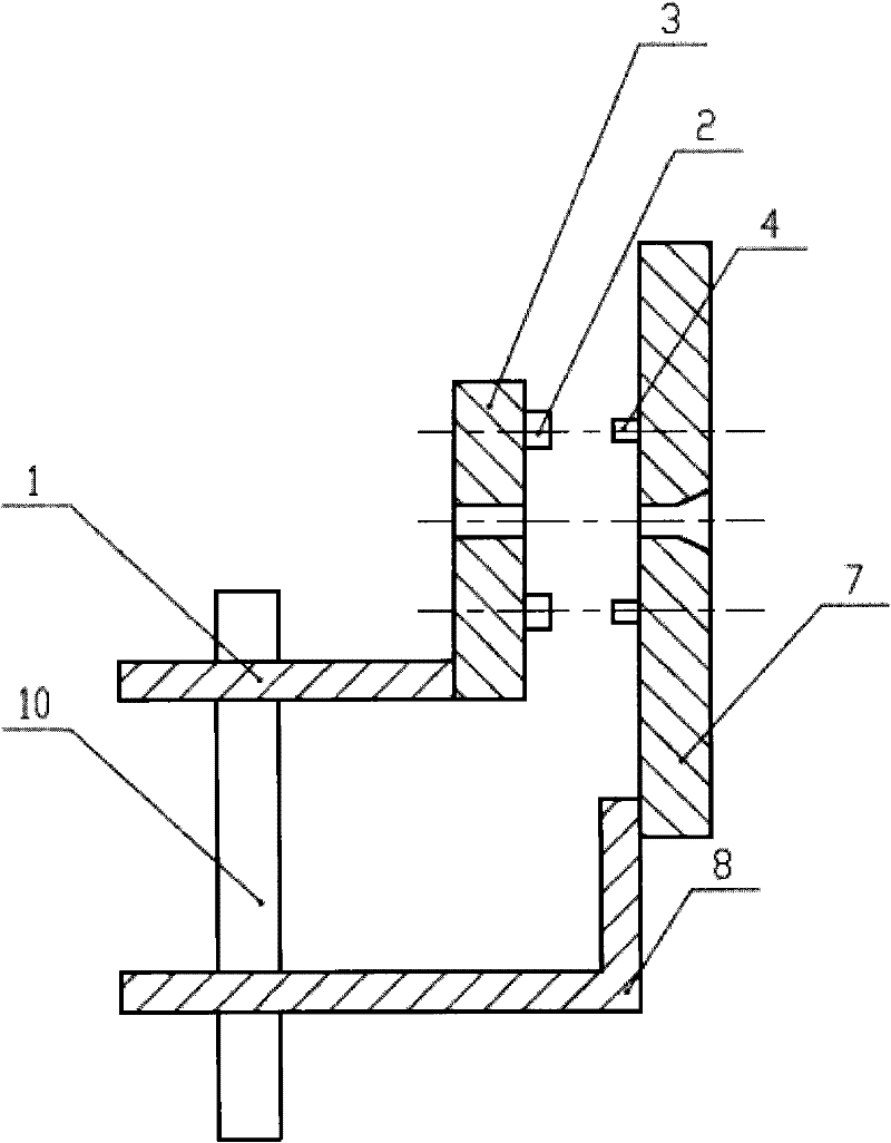
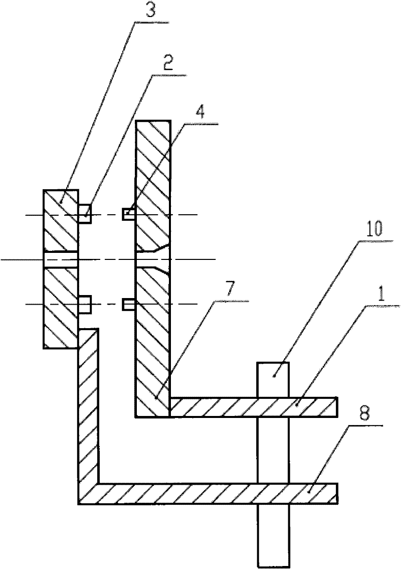
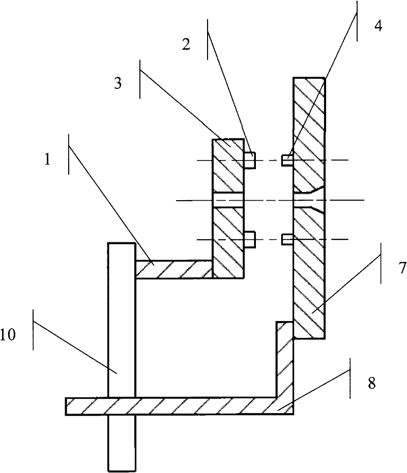
A split type ion source extraction electrode system comprises: a decelerating electrode 3, a shield cylinder 2, an insulator 4, an accelerating electrode 7, a deceleration electrode connecting rod 1, an accelerating electrode connecting rod 8 and an electrode pedestal 10. The shield cylinder 2 is installed on one side of the decelerating electrode 3, wherein the one side is facing the accelerating electrode 7. The insulator 4 is installed on one side of the accelerating electrode 7, is close to the shield cylinder 2 and is corresponding with the shield cylinder 2, wherein the one side is facing the decelerating electrode 3. The system is characterized in that: the decelerating electrode 3 is connected to and fixed on the pedestal 10 through the deceleration electrode connecting rod 1; the accelerating electrode 7 is connected to and fixed on the pedestal 10 through the accelerating electrode connecting rod 8 and because of a connection mode, the accelerating electrode 7 can accurately move forward and backward along an ion beam flow direction as required through forward and backward movements of the accelerating electrode connecting rod 8. An ion source extraction electrode structure is stabile and reliable. In an overheating situation, stress strain can not be generated between the accelerating electrode and the decelerating electrode. Therefore, electrode precision can not be lost. The system has many other advantages.

Description

technical field [0001] The invention relates to a semiconductor device manufacturing control system, that is, an ion implanter, in particular to a split ion source extraction electrode system for the ion implanter. Background technique [0002] In the ion implanter of semiconductor manufacturing process equipment, the ion source extraction system is one of the key components of the whole equipment. It is combined with the ion source body to form the core component of the ion implanter—the ion source system; it determines the ion implanter Many performance indicators not only determine the extracted beam size, extracted energy, extracted beam quality and beam stability performance of the ion source system, but also determine the beam transmission efficiency and The production efficiency of the whole machine. [0003] The ion source extraction electrode system of an ion implanter generally adopts an acceleration and deceleration three-electrode structure. Repeated experiments...

Claims


Application Information

Patent Timeline
Patent Type & Authority Applications(China)
IPC IPC(8): H01J37/04H01J37/02H01J37/32
Inventor 唐景庭伍三忠孙勇刘仁杰
Owner BEIJING ZHONGKEXIN ELECTRONICS EQUIP
Learn More