
In-phase and quadrature (IQ) unbalance compensation device and method

A balanced compensation and post-compensation technology, applied to baseband system components, multi-carrier systems, etc., can solve problems such as implementation troubles and corrections, and achieve the effect of small amount of calculation and simple structure

Active Publication Date: 2012-02-01
华力智芯(成都)集成电路有限公司
View PDF4 Cites 22 Cited by
  • Summary
  • Abstract
  • Description
  • Claims
  • Application Information

AI Technical Summary

Problems solved by technology

[0005] The disadvantage of the above method of estimating and compensating for IQ imbalance is that it is necessary to correct the radio frequency components or chips of the receiver, which is cumbersome to implement

Method used


Image

  • In-phase and quadrature (IQ) unbalance compensation device and method
  • In-phase and quadrature (IQ) unbalance compensation device and method
  • In-phase and quadrature (IQ) unbalance compensation device and method

Examples


Embodiment 1

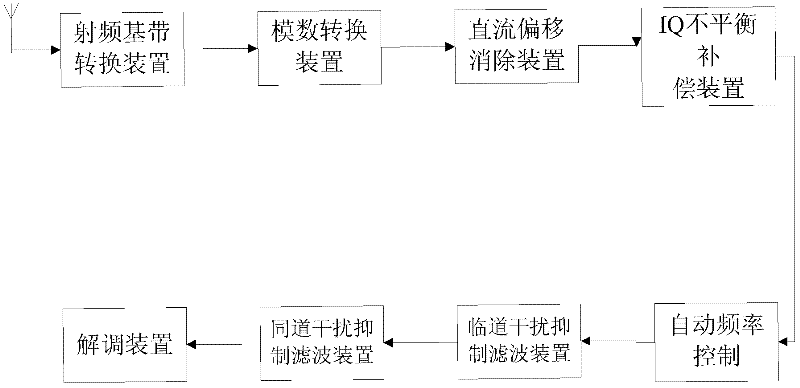
[0027] In the baseband sampling digital communication receiver of the single-carrier reception mode, the front end of the receiver refers to a component located at the front end of the demodulator and independent from the demodulator to improve the performance of the receiver. The structural diagram of the receiving front end of a baseband sampling digital receiver provided by the embodiment of the present invention is as follows figure 1 As shown, it includes: radio frequency baseband conversion device, analog-to-digital conversion device, DC offset elimination device, IQ imbalance estimation and compensation device, automatic frequency control device, adjacent channel interference suppression filter device and co-channel interference suppression filter device. The above-mentioned IQ imbalance estimation and compensation device is arranged after the analog-to-digital converter and the DC offset elimination device.

[0028] the above figure 1 The IQ imbalance estimation and c...

Embodiment 2

[0068] This embodiment provides an IQ imbalance compensation method, the specific processing flow is as follows Figure 7 As shown, the following processing steps are included:

[0069] Step 71 , using the output in-phase vector and quadrature vector of the previous symbol to calculate the estimated value of the phase imbalance error and the estimated value of the gain imbalance error of the current symbol.

[0070] The phase imbalance error estimation value of the current symbol is obtained by multiplying the in-phase vector and the orthogonal vector of the previous symbol output by the IQ imbalance compensation device:

[0071] E. x (l-1)=I(l-1)·Q(l-1)

[0072] The E x (1-1) represents the phase imbalance error estimated value of the current symbol, the I(1-1) represents the in-phase vector of the previous symbol output by the IQ imbalance compensation module, and the Q(1-1) represents the The orthogonal vector of the previous symbol output by the IQ imbalance compensati...


PUM


Abstract

The embodiment of the invention provides an in-phase and quadrature (IQ) unbalance compensation device and an IQ unbalance compensation method. The method mainly comprises the following steps of: computing a phase unbalance error estimation value and a gain unbalance error estimation value of a current symbol by utilizing an output in-phase vector and an output quadrature vector of a previous symbol; computing a phase compensation coefficient of the current symbol according to a phase compensation coefficient of the previous symbol and the phase unbalance error estimation value; computing a gain compensation coefficient of the current symbol according to a gain compensation coefficient of the previous symbol and the gain unbalance error estimation value; and compensating for a received in-phase vector and a received quadrature vector of the current symbol according to the phase compensation coefficient and the gain compensation coefficient, and outputting the compensated current symbol. The embodiment of the invention realizes a real-time time-domain IQ unbalance compensation way, and the way has a simple structure and is low in calculated amount, easy to realize and good in compensation effect.

Description

technical field [0001] The embodiments of the present invention relate to the technical field of communications, and in particular, to an IQ imbalance compensation device and method. Background technique [0002] In a digital satellite communication receiver using baseband sampling, the radio frequency or intermediate frequency signal is down-converted into a baseband signal, and the baseband signal is separated into an in-phase vector and a quadrature vector. Two sine waves with a difference of 90 degrees are used to achieve this. Then, the baseband signal is converted into a digital signal by an analog-to-digital converter. [0003] Since the above-mentioned conversion process is carried out in the analog operation domain, it will bring certain errors. Among them, the above two sine waves with the same amplitude and a phase difference of 90 degrees will have gain and phase errors between each other. This error may have a serious impact on the performance of the receiver....

Claims


Application Information

Patent Timeline
Patent Type & Authority Applications(China)
IPC IPC(8): H04L27/38H04L25/02
Inventor 刘解华安儒聪敬军杨陆刘凯
Owner 华力智芯(成都)集成电路有限公司
Learn More