
A wire bonding device with double bonding wire heads

A technology of wire bonding and wire bonding, which is applied in the direction of semiconductor devices, electrical components, circuits, etc., can solve the problem that the bonding efficiency of wire bonding machines is difficult to be greatly improved, and achieve the effect of improving cost performance and wire bonding efficiency

Inactive Publication Date: 2016-03-23
CENT SOUTH UNIV
View PDF5 Cites 0 Cited by
  • Summary
  • Abstract
  • Description
  • Claims
  • Application Information

AI Technical Summary

Problems solved by technology

However, limited by physical conditions, there is a physical limit to increase the bonding speed by improving the performance of unit components, and the efficiency cannot be infinitely improved, that is, it is difficult to greatly improve the bonding efficiency of a single wire bonding machine.

Method used


Image

  • A wire bonding device with double bonding wire heads
  • A wire bonding device with double bonding wire heads
  • A wire bonding device with double bonding wire heads

Examples


Embodiment Construction

[0013] The present invention will be further described below in conjunction with the accompanying drawings and specific embodiments.

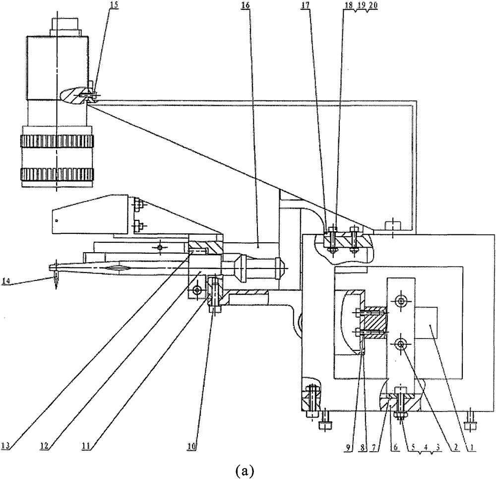
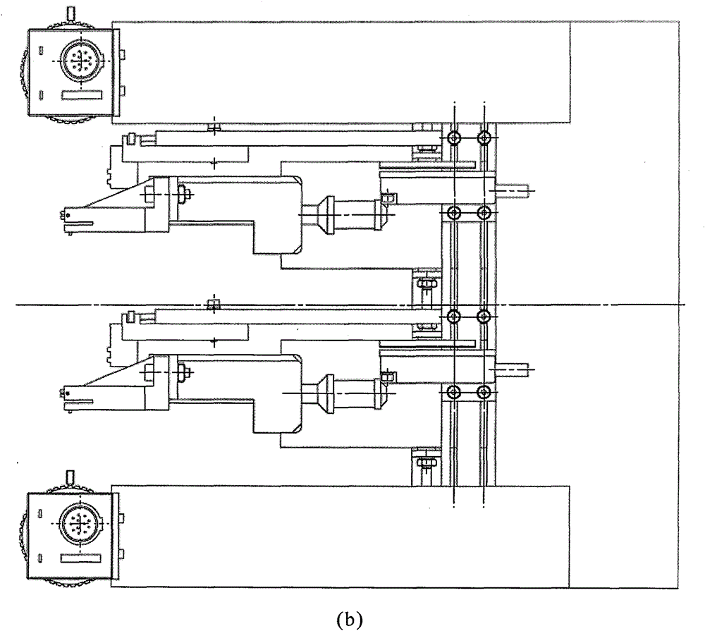
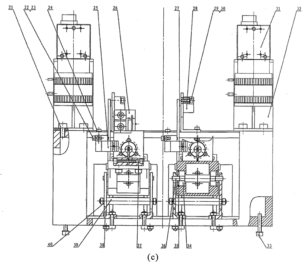
[0014] see figure 1 , the present invention includes two sets of identical welding wire heads, each welding wire head includes a wire clamp driving wire feeding system 26, an electronic ignition system 16, a horn 12, a splitting knife 14, a horn clamping seat 11, a horn Rod support 8, welding wire head rotating shaft 36, rotating shaft support bearing 34, shaft support frame 38, motor support 7, linear motor 1, linear encoder 28, vision system 31. Each welding wire head is fixed on the support frame 6 by connecting bolts 5, and the support frame is fixed on the planar motion platform by support fixing screws 33. Each welding wire head can rotate around the welding wire head rotating shaft 36 under the up and down driving action of the linear motor 1, and is combined with the wire clamp driving wire feeding system 26, the electronic ignition sy...


PUM


Abstract

The invention discloses a microelectronic chip wire bonding device with double bonding wire heads. The wire bonding device includes two sets of the same wire head. By manually adjusting the position of the connecting bolt on the groove on the lower part of the base of the wire head, the relative position and spacing between the two wire heads can be adjusted and adjusted. Change. Under the coordinated control of a common controller program, each wire bonding head can bond wires independently or synchronously, and the wire bonding efficiency is improved compared with the bonding machine with only a single bonding wire head. Each welding wire head includes a wire clamp drive wire feeding system, a firing rod support, a horn, a rivet, a horn clamping seat, a horn support, a wire head rotating shaft, a rotating shaft support bearing, a shaft support frame, Motor mounts, linear motors, linear encoders, vision systems, wire head holders. Each welding wire head is fixed on the welding wire head support by connecting bolts. In the present invention, a wire bonding device formed by two or even multiple wire bonding heads is configured on a bonding machine, and for different workpieces, through adjustment and programming, division of labor and cooperation are performed to jointly complete the wire interconnection bonding wire between the chip and the substrate. task, the chip bonding efficiency can be doubled.

Description

technical field [0001] The invention relates to a wire bonding device for microelectronic chip packaging, in particular to a wire bonding device with two welding heads working together. technical background [0002] Wire bonding is the dominant method for microelectronic packaging. In order to increase the speed of wire bonding, a lot of improvements have been made in the driving source, bonding mechanism, even the feeding and discharging system and the layout of the workpiece, including the direct drive of linear motors widely used in the driving source, instead of stepping motors. The ball screw transmission mode, the mechanism adopts a new mechanism combining parallel and series, the chips of the same type are arranged in an array at equal intervals, etc., and the bonding motion performance is significantly improved. However, limited by physical conditions, there is a physical limit to increase the bonding speed by improving the performance of unit components, and the ef...

Claims


Application Information

Patent Timeline
Patent Type & Authority Patents(China)
IPC IPC(8): H01L21/60
CPCH01L24/78H01L2224/78301H01L2924/00014H01L2224/78H01L2224/48H01L2924/00012
Inventor 李群明韩雷邓华张世伟
Owner CENT SOUTH UNIV
Learn More