Evaporation source and evaporation coating device
A technology of a coating device and an evaporation source, applied in the field of coating devices, can solve the problem of low utilization rate of source materials, and achieve the effects of multi-regional temperature control, high thickness adjustability, and stable temperature
- Summary
- Abstract
- Description
- Claims
- Application Information
AI Technical Summary
Problems solved by technology
Method used
Image


Examples
Embodiment 1
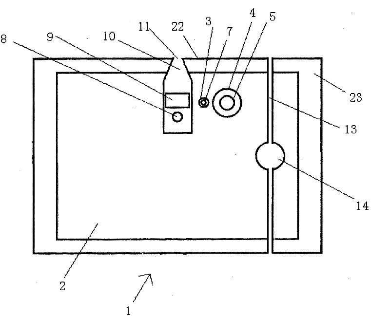
[0055] like figure 1 As shown, the evaporation source 1 is an integrated structure, including a temperature control module (see image 3 ), carrier gas inlet module (see Figure 4 and Figure 5 ), a feeding module, an exhaust module and a thermal insulation module 23, the five modules are all located in one evaporation source body 2, and the evaporation source body 2 is an integral structure formed by casting or cutting. The material of the evaporation source body is silicon carbide ceramics with a melting temperature of 2700°C and a thermal conductivity of 360w / mk. The material with high temperature resistance and good thermal conductivity is selected as the material of the evaporation source body 2, and the functional modules that make up the coating equipment are integrated into a single structure, that is, the evaporation source body 2, so that stable and uniform temperature control can be achieved, and the composition Evaporation source 1 with simple and compact struct...
Embodiment 2
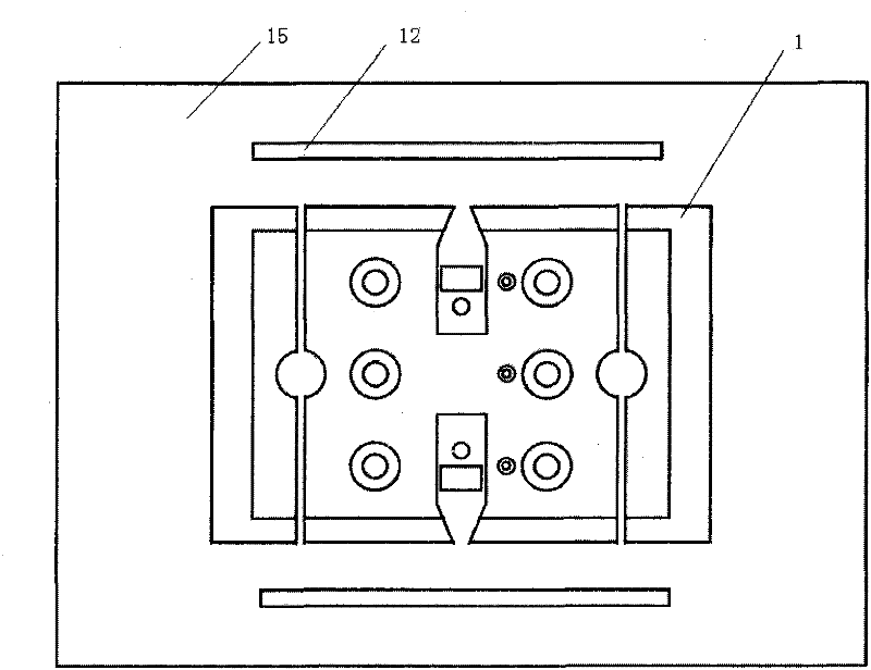
[0062] For the structure of evaporation source 1, see figure 2 , the difference from Embodiment 1 is that the evaporation source 1 has two opposite evaporation source working surfaces 22, and the temperature control module includes three pairs of ultraviolet heaters 5 and three thermocouples 7, the ultraviolet heater 5 and the thermocouple 7 A temperature controller 6 is connected between them, and three temperature controllers 6 are located outside the evaporation source body 2; the carrier gas inlet module includes two carrier gas distribution pipes 8 and two carrier gas inlets 17; the feeding module includes two source material chambers 9 and two injection ports 11; the exhaust module includes two waste gas outlets 13 and two exhaust pipes 14.
[0063] The material of the evaporation source body 2 is graphite ceramics with a melting temperature of 3500°C and a thermal conductivity of 150w / mk.
[0064] like image 3 As shown, the evaporation coating device 16 includes the...
Embodiment 3
[0067] The structure of the evaporation source 1 is the same as that of the second embodiment, except that there is no buffer chamber 10 between the source material chamber 9 and the source material steam injection port 11, the material of the evaporation source body is stainless steel, the melting temperature is 1400°C, and the thermal conductivity is 70w / mk. The material of the carrier gas distribution pipe 8 is silicon carbide with a melting temperature of 2700°C and a thermal conductivity of 360w / mk. The evaporation source body 2 has a spherical structure, and the heat insulation module 23 is composed of four arc-shaped heat insulation plates, surrounding the outer surface of the evaporation source body 2 .
PUM
| Property | Measurement | Unit |
|---|---|---|
| melting point | aaaaa | aaaaa |
| pore size | aaaaa | aaaaa |
| melting point | aaaaa | aaaaa |
Abstract
Description
Claims
Application Information
 - R&D
- Intellectual Property
- Life Sciences
- Materials
- Tech Scout
- Unparalleled Data Quality
- Higher Quality Content
- 60% Fewer Hallucinations
Browse by: Latest US Patents, China's latest patents, Technical Efficacy Thesaurus, Application Domain, Technology Topic, Popular Technical Reports.
© 2025 PatSnap. All rights reserved.Legal|Privacy policy|Modern Slavery Act Transparency Statement|Sitemap|About US| Contact US: help@patsnap.com