
Light-emitting diode (LED) lamp control circuit having key element overvoltage protection function

A technology of LED lamps and overvoltage protection, which is applied in the direction of emergency protection circuit device for limiting overcurrent/overvoltage, emergency protection circuit device, lamp circuit layout, etc., and can solve the problem of LED lamp dead light scrapping and switching surge impact , fan damage and other problems, to avoid excessive instantaneous voltage, reliable control, and reduce the effect of circuit components

Inactive Publication Date: 2012-01-04
NANKER GUANGZHOU SEMICON MFG
View PDF8 Cites 16 Cited by
  • Summary
  • Abstract
  • Description
  • Claims
  • Application Information

AI Technical Summary

Problems solved by technology

However, in an environment with multiple LED lamps, if multiple lamps are turned on at the same time, switching surges will also occur, and the voltage will fluctuate in a large range instantaneously. Once the instantaneous voltage is too high, it may cause shock to the fan. Even damage the fan
[0005] To sum up, the key components in the lighting circuit of LED lamps may be damaged due to the impact of switching surges, resulting in the death of LED lamps and scrapping

Method used


Image

  • Light-emitting diode (LED) lamp control circuit having key element overvoltage protection function
  • Light-emitting diode (LED) lamp control circuit having key element overvoltage protection function
  • Light-emitting diode (LED) lamp control circuit having key element overvoltage protection function

Examples


Embodiment 1

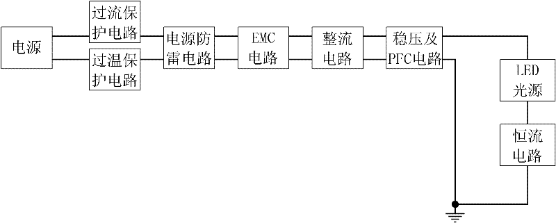
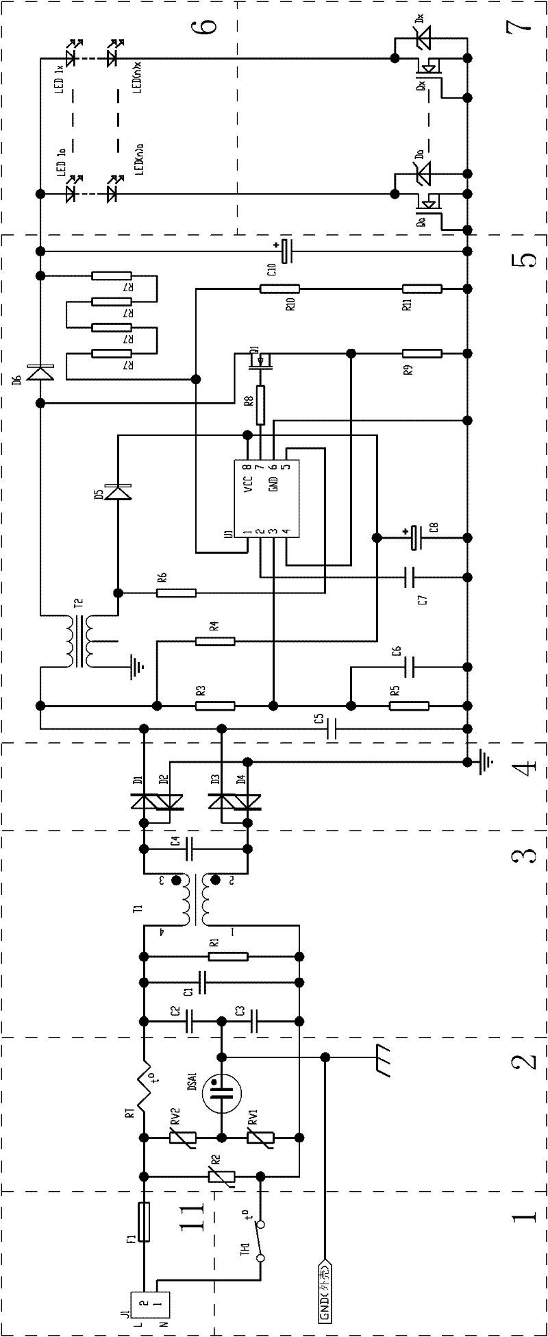
[0025] like figure 1 , figure 2As shown, the LED lamp with overvoltage protection function of key components in this embodiment includes a radiator for passive heat dissipation, and the LED lamp control circuit with overvoltage protection function of key components includes a first temperature control switch circuit 1, an overcurrent Protection circuit 11, power lightning protection circuit 2, EMC circuit 3, voltage stabilizer and PFC circuit 5, LED light source load 6, rectifier circuit 4 that converts alternating current into direct current, and stabilizes voltage and current for the LED light source load 6 Constant current circuit 7, the overcurrent protection circuit 11 is connected to the input end of the power supply, the overcurrent protection circuit 11 includes an overcurrent protection fuse F1 for overcurrent and short circuit protection, the power lightning protection circuit 2 is connected to the overcurrent protection circuit 11 and the first temperature control...

Embodiment 2

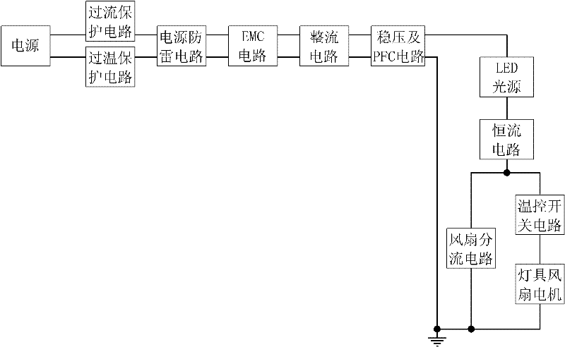
[0027] like image 3 , Figure 4 As shown, the LED lamp control circuit with the overvoltage protection function of key components in this embodiment can be applied to the high bay lamp of the cold storage. The LED lamp includes a cooling fan for active heat dissipation and a radiator for passive heat dissipation, which is related to the The difference between the first embodiment is that this embodiment also includes a lamp fan motor 10 , a fan shunt circuit 8 , and a second temperature control switch circuit 9 , and the second temperature control switch circuit 9 is connected in series with the lamp fan motor 10 . In parallel with the fan shunt circuit 8, the fan shunt circuit 8 is connected in parallel with a second Zener diode Dfan, and the voltage regulator operating point of the second Zener diode Dfan can be based on the power of the lamp and the actual circuit situation. and other factors are selected as a specific voltage between 6 and 24V DC, and the fan shunt circu...


PUM


Abstract

The invention discloses a light-emitting diode (LED) lamp control circuit having a key element overvoltage protection function and characteristics of simplicity in structure, reliability in control and low cost. The LED lamp control circuit comprises an LED light source load (6), a rectifying circuit (4) which converts an alternating current into a direct current, and a constant current circuit (7) which stabilizes the voltage and the current of the LED light source load (6), wherein the LED light source load (6) comprises at least one group of a plurality of LEDs which are connected with one another in series; the constant current circuit (7) comprises at least one group of constant current source devices; each group of constant current source devices comprise at least one depletion mode field effect transistor; a drain of each depletion mode field effect transistor is a contact; a source and a grid of each depletion mode field effect transistor are short-circuited to form another contact; and each group of the constant current source devices are parallelly connected with a first zener diode with a special voltage of which a voltage stabilization operating point is 20 to 80-volt direct current. The LED lamp control circuit can be applied in the field of LED lighting circuits.

Description

technical field [0001] The invention relates to an LED lamp control circuit with an overvoltage protection function of key elements. Background technique [0002] At present, the application of LED is more and more extensive, and LED lamps for daily indoor and outdoor lighting are also becoming more and more popular. The current LED lighting generally needs to use a constant current drive circuit to provide stable direct current to the LED and ensure the normal operation and service life of the LED. The current constant current drive circuit is generally complex in structure. [0003] The applicant has taken the lead in applying depletion-mode MOSFET devices to LED lighting drive circuits, providing current buffering with a single device, ensuring that the LED current is stable and not impacted, and has achieved good results in practical applications. However, in an environment where multiple LED lamps are used at the same time, if multiple lamps are turned on at the same t...

Claims


Application Information

Patent Timeline
Patent Type & Authority Applications(China)
IPC IPC(8): H05B37/02H02H9/04F21V29/02F21Y101/02F21V29/61
Inventor 吴俊纬
Owner NANKER GUANGZHOU SEMICON MFG
Learn More