Optical coupler

An optocoupler, photosensitive technology, applied in optocoupler, optocoupler. , In the field of photoelectric isolators or photocouplers, it can solve the problems of high precision requirements of lead frames, difficult process realization, and high insulation withstand voltage. It is easy to control the CTR value, high photoelectric conversion efficiency, and excellent insulation withstand voltage. performance effect

Active Publication Date: 2012-01-04
XIAMEN HUALIAN ELECTRONICS CO LTD
View PDF4 Cites 9 Cited by
  • Summary
  • Abstract
  • Description
  • Claims
  • Application Information

AI Technical Summary

Problems solved by technology

But because they are face-to-face, the thickness of the two chips and the thickness of the two lead frames have reached or approached 1.5mm, and the insulation distance between the infrared end and the photosensitive end is limited by the total height of the optocoupler. The pressure cannot be very high; and the precision requirements for the lead frame are very high, and the process is difficult to realize

Method used


Image

  • Optical coupler
  • Optical coupler
  • Optical coupler

Examples


Embodiment Construction

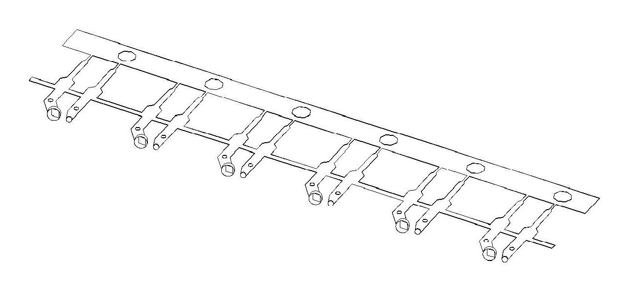
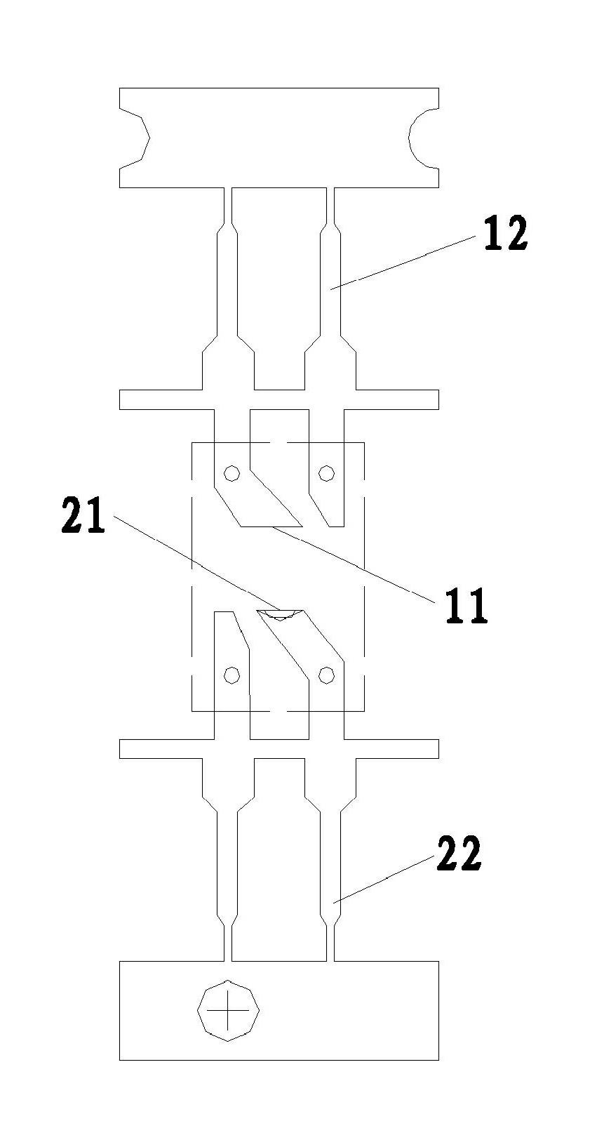
[0025] The present invention will be further described in conjunction with the accompanying drawings and specific embodiments. Although the chip-loading area of ​​the infrared end lead frame and the chip-loading area of ​​the photosensitive end lead frame in the claims of the present invention can be cup-shaped or plane, the following examples only use the chip-loading area of ​​the infrared end lead frame as a cup shape, and the photosensitive end lead The slide-loading area of ​​the frame is described as a flat surface.

[0026] refer to figure 1 and figure 2 As shown, the lead frame of the optocoupler is divided into an infrared end lead frame 2 and a photosensitive end lead frame 1, and a plurality of infrared end lead frame units or photosensitive end lead frame units form a row of infrared end lead frames or photosensitive end lead frames. After the package is manufactured, the lead frame pins are punched to separate them into independent components.

[0027] For th...


PUM


Abstract

The invention relates to a photoelectric element, especially to an optical coupler, which is also known as a photoisolator or an optoelectronic coupler or is called an optocoupler for short. According to the invention, a lead frame of an optical coupler falls into an infrared end lead frame and a photosensitive end lead frame; planes of glass sliding areas of the infrared end lead frame and the photosensitive end lead frame are perpendicular to a plane of the lead frame; infrared light emitting elements are installed on the infrared end lead frame and photosensitive elements are installed on the photosensitive end lead frame; the infrared end lead frame and the photosensitive end lead frame are fixed on a same plane and there is an enough insulation distance between the infrared end lead frame and the photosensitive end lead frame; the photosensitive elements directly face the infrared light emitting elements; outer surfaces of the glass sliding areas of the infrared end lead frame and the photosensitive end lead frame are cladded with transparent colloids, which are in ellipse shapes; and the infrared end lead frame, the photosensitive end lead frame and the transparent colloids are wrapped with a packaging shell tube. According to the invention, the optical coupler not only has good insulation and pressure resistant performances that a reflective optocoupler has, but also has a high photoelectric conversion efficiency that a direct-injection optocoupler has; besides, a CTR value is convenient for control.

Description

technical field [0001] The present invention relates to an optoelectronic element, especially an optocoupler (optical coupler, English abbreviation is OC), also known as an optoelectronic isolator or optocoupler, or optocoupler for short. Background technique [0002] An optocoupler is a device that transmits electrical signals through light as a medium. Usually, the light emitter (infrared light-emitting diode chip) and the light receiver (photosensitive chip) are packaged in the same package. When the input terminal is powered on, the light emitter emits light, and the light receiver generates photocurrent after receiving the light, which flows out from the output terminal, thus realizing the "electricity-optical-electricity" conversion. At present, there are two main production methods of optocouplers: one is reflective type, and the other is direct type. [0003] refer to Figure 9a and Figure 9b As shown, the reflective type is to form an ellipsoid by dispensing glue...

Claims


Application Information

Patent Timeline
Patent Type & Authority Applications(China)
IPC IPC(8): H01L25/16H01L23/495H01L23/31
CPCH01L2224/48091H01L2224/48247H01L2924/1301
Inventor 段果陈巍
Owner XIAMEN HUALIAN ELECTRONICS CO LTD
Why Eureka
Try Eureka