Hydraulic system applied for die hydraulic testing machine

A hydraulic system and testing machine technology, applied in the testing of mechanical components, testing of machine/structural components, measuring devices, etc., can solve problems such as economic losses, customer production time delays, and problems with ejection, and achieve the goal of solving losses Effect

Inactive Publication Date: 2012-01-04
NINGBO SOUTH MOLD & PLASTIC
View PDF5 Cites 2 Cited by
  • Summary
  • Abstract
  • Description
  • Claims
  • Application Information

AI Technical Summary

Problems solved by technology

[0003] 1. When the mold is tested on the machine, if the mold has the following problems: there is a defect in the ejector mechanism, such as impurities that have not been cleaned up during the mold assembly, resulting in problems with the ejection, and it is impossible to continue the mold trial; the rubber in the mold cylinder The quality of the ring is not good enough, resulting in oil leakage in the mold cylinder; when the top block of the mold is loose or dangerous, it is necessary to remove the mold from the machine and re-adjust and process the mold, which will cause trouble and damage caused by rework The loss is very huge, especially on large molds, such as the production of bumpers, dashboards, door panels, sub-dashboards and other molds...

Method used


Image

  • Hydraulic system applied for die hydraulic testing machine
  • Hydraulic system applied for die hydraulic testing machine
  • Hydraulic system applied for die hydraulic testing machine

Examples


Embodiment Construction

[0022] The present invention will be further described below in conjunction with the accompanying drawings and specific embodiments.

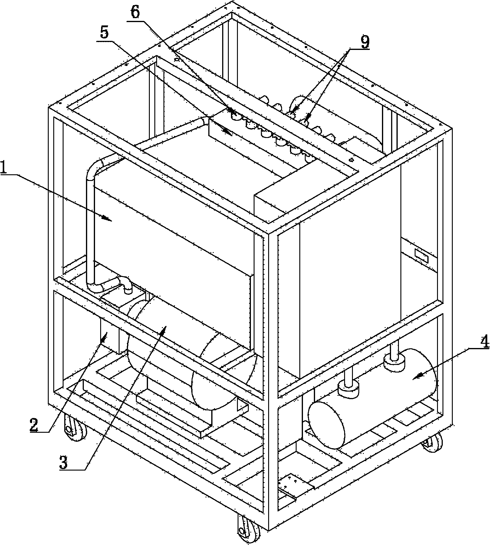
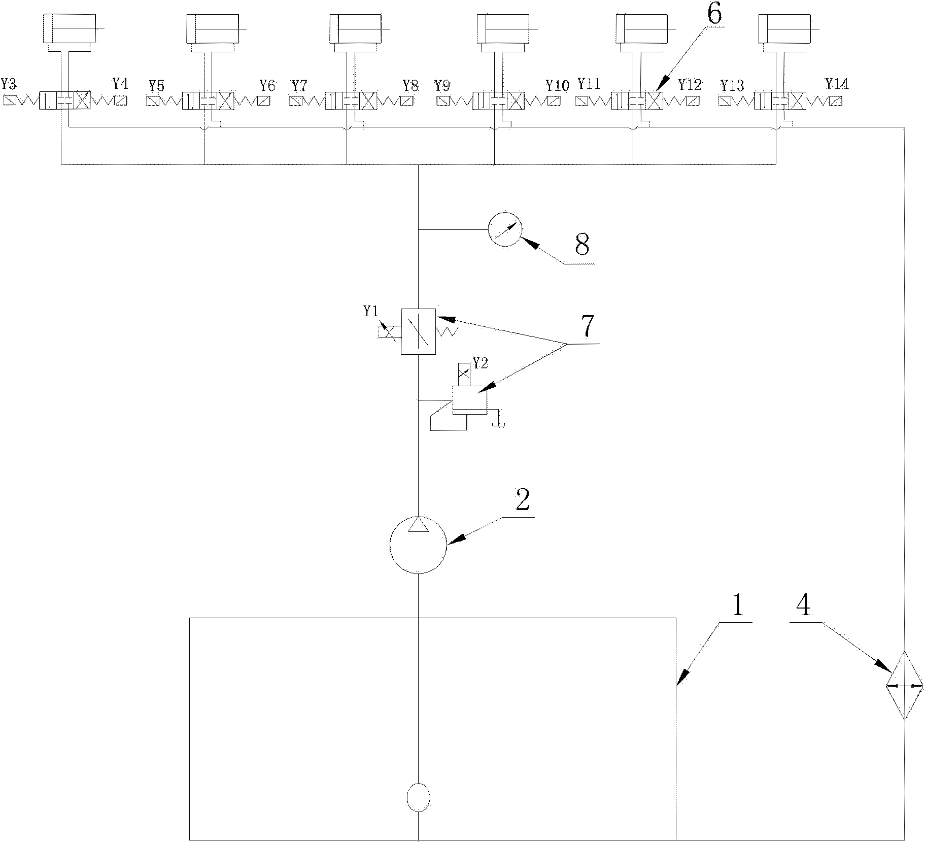
[0023] Such as Figure 1 to Figure 3 As shown, the hydraulic system for the mold hydraulic testing machine of the present invention includes an oil tank 1 filled with hydraulic oil, a hydraulic pump 2, a motor 3 connected to the pump shaft, and a proportional valve 7 for controlling the pressure and flow of the hydraulic oil , valve plate 5, six solenoid valves 6 installed on the valve plate 5 for controlling the circulation or cut-off of the hydraulic channel, and a cooler 4 for cooling hydraulic oil. The oil tank 1 communicates with the hydraulic pump 2 through the pipeline, the hydraulic pump 2 communicates with the proportional valve 7 through the pipeline, the proportional valve 7 communicates with the valve plate 5 through the pipeline, and the valve plate 5 communicates with the detected mold through the pipeline. The oil cylinder is co...


PUM


Abstract

The invention relates to a hydraulic system applied for a die hydraulic testing machine. The hydraulic system comprises: a fuel tank; a hydraulic pump; a motor, which is connected with a pump shaft; a proportioning valve, which is used for controlling a pressure and a flow of hydraulic oil; a valve plate; a plurality of magnetic valves, which are installed on the valve plate and are used for controlling circulation and cut off of a hydraulic channel; and a cooler, which are used for cooling the hydraulic oil. The fuel tank is communicated with the hydraulic pump through a pipeline; the hydraulic pump is communicated with the proportioning valve through a pipeline; the proportioning valve is communicated with the valve plate through a pipeline; the valve plate is communicated with an oil cylinder of a detected die through a pipe line; the valve plate is also communicated with the cooler through a pipeline; and the cooler is communicated the fuel tank through a pipeline; therefore, a hydraulic detection and cooling loop is formed. According to the hydraulic system applied for the die hydraulic testing machine provided in the invention, die detection can be carried out when the die is assembled, after the die assembly is completed, before the die trial on an injection machine and before the die transportation.

Description

technical field [0001] The invention relates to the technical field of mold hydraulic system and ejection system detection, in particular to a hydraulic system for a mold hydraulic testing machine. Background technique [0002] At present, mold manufacturers generally can only test molds, especially injection molds, by testing molds on injection molding machines, and there are a series of shortcomings in testing molds on injection molding machines: [0003] 1. When the mold is tested on the machine, if the mold has the following problems: there is a defect in the ejector mechanism, such as impurities that have not been cleaned up during the mold assembly, resulting in problems with the ejection, and it is impossible to continue the mold trial; the rubber in the mold cylinder The quality of the ring is not good enough, resulting in oil leakage in the mold cylinder; when the top block of the mold is loose or dangerous, it is necessary to remove the mold from the machine and re...

Claims


Application Information

Patent Timeline
IPC IPC(8): G01M13/00
Inventor 杨宝金
Owner NINGBO SOUTH MOLD & PLASTIC
Why Eureka
Try Eureka