Rifle-shaped felting needle

A technology of laiford thread and felting needle is applied in the field of equipment for producing non-woven fabrics, which can solve the problems of high friction coefficient, damage to the performance of non-woven fabrics, fiber damage, etc. The effect of pulling force and improving performance

Inactive Publication Date: 2012-01-04
青岛锦钻针业有限公司
View PDF6 Cites 2 Cited by
  • Summary
  • Abstract
  • Description
  • Claims
  • Application Information

AI Technical Summary

Problems solved by technology

Such as: ceramic fiber, carbon fiber, glass fiber, stainless steel fiber, aramid fiber and other non-lubricating fibers. Due to the high brittleness of the fiber itself, the friction between the fiber and the fiber is large, and the friction coefficient is large. Therefore, the existing needle The strain on the fiber itself is severe, and the fiber itself is damaged, resulting in defects such as delamination of the fiber web layer, which directly destroys the performance of the nonwoven.
[0005] The performance indicators of carbon fiber components used in aerospace are extremely strict, especially requiring high entanglement and cohesion between fibers. However, the use of existing needle-woven nonwovens cannot meet the relevant requirements. Require

Method used


Image

  • Rifle-shaped felting needle
  • Rifle-shaped felting needle
  • Rifle-shaped felting needle

Examples


specific Embodiment 1

[0060] Specific embodiment 1: (single fiber storage tank)

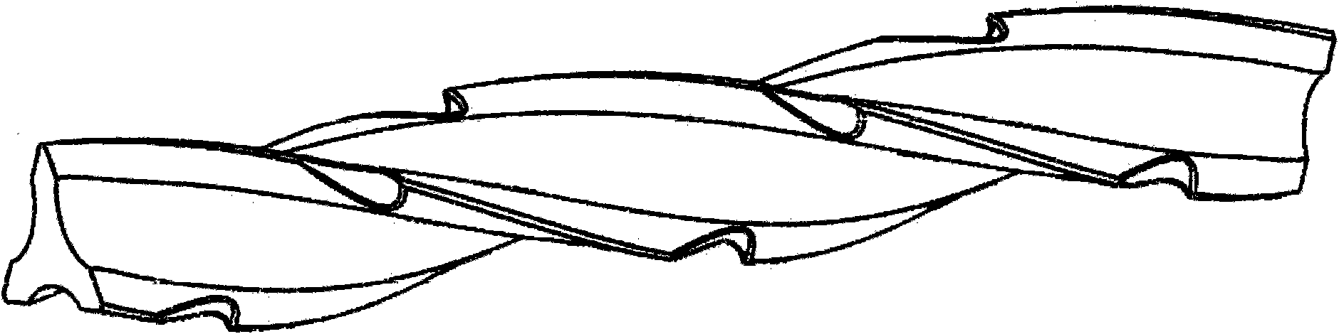
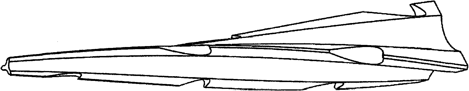
[0061] A rifle-shaped needle, composed of an integral needle shaft, a middle section and a working section, the ridge line 1 of the working section is in the shape of a rifle, and there is a gap between two adjacent ridge lines 1 Fiber storage tank 2. The fiber storage tank 2 is set as a groove, and at least one fiber storage tank 2 is arranged between two adjacent ridge lines 1 . The working section of the pricker is set in a triangular (conical) column shape, the ridge lines 1 of the working section are in the shape of a rifle, and a fiber storage tank 2 is arranged between two adjacent ridge lines 1, and the fiber storage tank 2 The cross-sectional shape is arc-shaped (such as Figure 1-3 shown), triangles (such as Figure 4-6 shown), trapezoidal (such as Figure 7-9 shown), rectangle (as shown in Figure 10-12).

[0062] The working section of the pricker is set in a square (cone) column shape, the ridge lines...

specific Embodiment 2

[0063] Specific embodiment 2: (double fiber storage tank)

[0064] The working section of the puncture needle is set as a triangular (conical) column, and both sides of the ridge line of the triangular column are provided with a fiber storage tank, and the cross-sectional shape of the fiber storage tank is arc-shaped (such as Figure 19-24 shown), triangles (such as Figure 25-27 As shown), trapezoid (as shown in Figure 28-30), rectangle (as shown in Figure 31-33), parabolic (as shown in Figure 34-36), involute (as shown in Figure 37-39).

[0065] The working section of the pricker is set in a star-shaped (tapered) column, and both sides of the longer-diameter ridge line of the star-shaped column are provided with fiber storage tanks (such as Figure 40-45 shown).

[0066] Barbed hooks are arranged on the ridge line, and the number of barbed hooks is set to 1-32.


PUM


Abstract

The invention relates to a rifle-shaped felting needle. The felting needle consists of a needle rod, a middle section and a working section which are integrated; the ridge of the working section is rifle-shaped; and fiber storage grooves are formed between the adjacent ridges. The designed needle form is particularly suitable for weaving of thick and compact fibers, and weaving of nonwoven fabric which has high fragility (such as ceramic fiber, glass fiber and the like) or nonwoven fabric which has high friction force (such as carbon fiber, stainless steel fiber, aramid fiber, high-strength polyethylene fiber and the like). The felting needle can be used for weaving carbon fiber members used for aerospace.

Description

technical field [0001] The invention relates to a device for producing nonwovens, in particular to a needling machine part. Background technique [0002] The needle is an important device for the production of non-woven fabrics. It punctures the fiber web layer up and down at high speed, so that the fibers are entangled with each other to form various non-woven fabrics. The traditional non-woven needle is composed of a needle bar, a middle needle bar and a hook body made of one piece. The hook body is a triangular body, each edge is peak-shaped, and a plurality of hook teeth are arranged in sequence on it. Since multiple hook teeth are arranged in a straight line, during the puncture process, when the first hook teeth randomly hook fibers, the probability of subsequent hook teeth hooking fibers will be significantly reduced, resulting in low work efficiency. [0003] The patent number is: 200620101167.8, and the utility model patent titled "Spiral Non-woven Pricking Needle"...

Claims


Application Information

Patent Timeline
Patent Type & Authority Applications(China)
IPC IPC(8): D04H18/00
Inventor 薛淞薛同乐
Owner 青岛锦钻针业有限公司
Why Eureka
Try Eureka