
Numerically-controlled foam block cutting all-in-one machine

An all-in-one machine and foam block technology, which is applied in metal processing and other directions, can solve the problems of low processing precision, need more equipment, and tediousness, etc., and achieve the effect of improving processing accuracy and production efficiency, reducing labor intensity and labor force, and compact and reasonable structure.

Inactive Publication Date: 2012-01-04
SHANDONG UNIV
View PDF9 Cites 18 Cited by
  • Summary
  • Abstract
  • Description
  • Claims
  • Application Information

AI Technical Summary

Problems solved by technology

In the past, the cutting process of the foam block was relatively cumbersome, and several different equipments were required to process each surface of the foam block separately. After the completion, transfer the foam block to another edge trimming equipment to cut both sides of the foam block. After the two sides are completed, turn the foam block 90 degrees or transport it to another edge trimming equipment. The other two sides are cut, and after each side is cut, the foam block is transported to another equipment, and the foam block is sliced.
In this way, it takes at least 4 times of handling and clamping and 3 or 4 equipment processing to complete these processes, which is time-consuming and laborious, requires a lot of equipment, and the processing accuracy of repeated clamping is also low.
[0003] At the same time, there is no detection device on the existing blister cutting equipment, such as "Plastic Bubble Cutting Machine" disclosed in Chinese patent document CN201168983 and a kind of blister cutting machine disclosed in CN201231508, which cannot detect the removal amount of the uneven top surface. Does not meet minimum removal of uneven sides

Method used


Image

  • Numerically-controlled foam block cutting all-in-one machine
  • Numerically-controlled foam block cutting all-in-one machine
  • Numerically-controlled foam block cutting all-in-one machine

Examples


Embodiment Construction

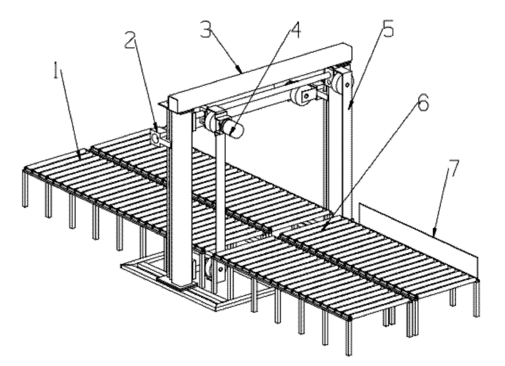
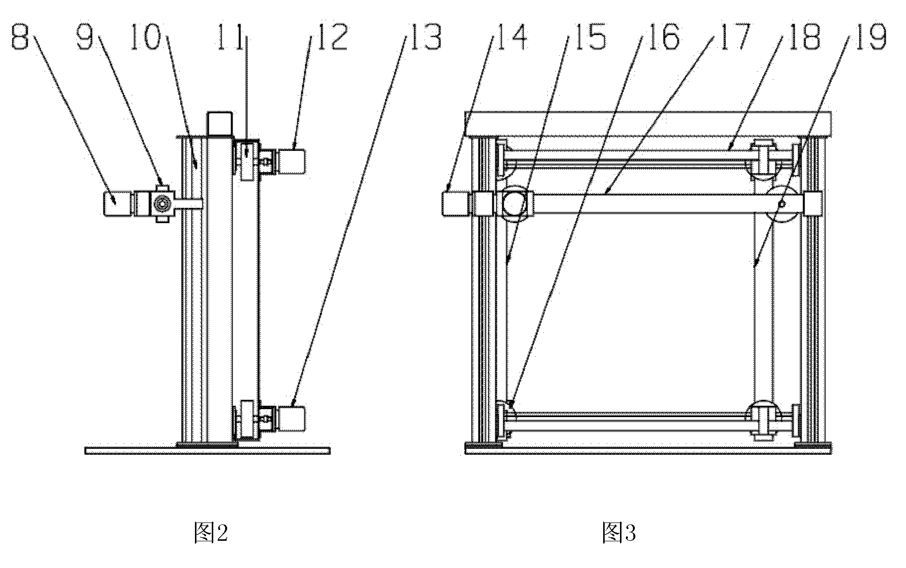
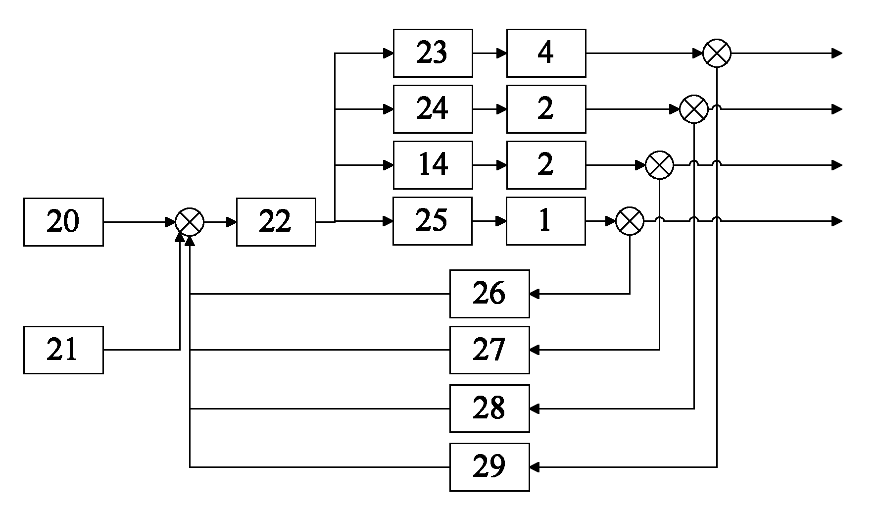
[0018] Such as figure 1 , figure 2 and image 3 As shown, the CNC foam block cutting integrated machine of the present invention includes a working platform 1, a gantry tower 3, a top and front and rear cutting device 2, a left side cutting device 4 and a right side cutting device 5. In the following narrative, the figure 1 The direction to the left of is forward. The gantry tower 3 spans the left and right sides of the working platform 1. The working platform 1 passes through the gantry tower 3 and is set on the ground. The right side of the working platform 1 is provided with a positioning device 7. The positioning device 7 is adjusted and fixed on the On the working platform 1, it is used for positioning the foam block during cutting. The foam block is clamped on the working platform 1 to perform positioning in the left and right direction through the positioning device 7, that is, positioning perpendicular to the moving direction of the workpiece. The positioning devic...


PUM


Abstract

The invention discloses a numerically-controlled foam block cutting all-in-one machine, which comprises a working platform, a portal tower frame, a top, front and back edge cutting device, a left side edge cutting device, a right side edge cutting device, a three-dimensional (3D) vision sensor and a control system, wherein a workpiece movement mechanism is arranged on the working platform; a front-back movement distance detection device is arranged between the working platform and the portal tower frame; a 3D vision sensor is arranged at the top of the portal tower frame; the top, front and back edge cutting device is arranged in the front of the portal tower frame through a lifting and descending transmission mechanism; the left side edge cutting device is arranged on the left side of the rear part of the portal tower frame through a horizontal transmission mechanism; the right side edge cutting device is directly arranged on the right side of the rear part of the portal tower frame in a fixed manner; and all electric parts and the sensor are respectively connected with the control system. By adoption of the numerically-controlled foam block cutting all-in-one machine, five facescan be automatically cut through one-time clamping, foam blocks can be sliced, automatic processing is realized, processing accuracy and production efficiency are improved, the waste of materials is reduced, and production cost is reduced.

Description

technical field [0001] The invention relates to a mechanical device for cutting foam blocks, belonging to the technical field of foam block cutting. Background technique [0002] Foam blocks (such as polyurethane foam blocks, etc.) are widely used and require a large amount. They are widely used in refrigeration equipment, industrial equipment insulation, building materials, automotive roof interiors, sound-absorbing and shock-absorbing materials, etc. Different uses and different application conditions have different cutting and processing sizes and methods for blister blocks, and more types of cutting equipment are required. The surface of the foamed foam block is not completely flat, some places are raised, some places are sunken and uneven. Blister cutting is to remove the unevenness and obtain a complete flat plane, that is, the position of the cutting tool should be at the lowest point of the uneven plane to minimize the amount of removal. The primary process of cutt...

Claims


Application Information

Patent Timeline
IPC IPC(8): B26D1/12B26D5/20B26D7/06B26D7/28B26D7/26
Inventor 林明星李永
Owner SHANDONG UNIV
Learn More