
Calibrating method for electronic compass

An electronic compass and calibration method technology, applied in the field of directional navigation, can solve the problems of not substantially improving the measurement accuracy of the magnetic compass, deterioration of fitting performance, and large amount of data

Active Publication Date: 2012-07-04
BEIJING INSTITUTE OF TECHNOLOGYGY
View PDF0 Cites 4 Cited by
  • Summary
  • Abstract
  • Description
  • Claims
  • Application Information

AI Technical Summary

Problems solved by technology

Yuan Zhirong's paper "Full Attitude Error Compensation of Three-axis Magnetic Heading Sensor" proposes to divide the compass error into orthogonal error, zero position and sensitivity error to compensate separately. This method has high compensation accuracy, but a non-magnetic turntable is required in the compensation process , and the computer is required to automatically measure the maximum and minimum values ​​of the X and Y axis sensor outputs when the compass rotates one revolution, the calibration process is more complicated, and the equipment requirements are higher; And Shao Tingting, Ma Jiancang's paper "Study on the Compensation Algorithm for Tilt and Error of the Electronic Compass" uses the least squares method to compensate the electronic compass. The size of the sampled data will have a great impact on the fitting results. If the amount of data is too small, the compensation effect will not be good. If the amount of data is too large, the fitting performance will deteriorate; Research on Error Correction Method" and Qi Zhang, Liang-shui Lei, Jiang Fan, Song Liu's paper "Autocalibration of a magnetic compass without heading reference" proposed a compensation method based on the ellipse assumption error model, because the ellipse assumption model is only based on the experiment According to experience, the compensation effect is not very ideal due to the lack of theoretical proof; Chao Min, Jiang Dongfang, and Wen Caihong’s paper "Magnetic Compass Error Analysis and Calibration" uses analytical methods to establish a more accurate model of the magnetic direction measurement system, and the electronic compass Compensation is carried out under horizontal conditions, but there are many parameters to be identified during the compensation process (up to 9), and the results show that the compensation effect is similar to the ellipse hypothesis model; Hao Zhenhai, Huang Shengguo's paper "Composite Heading System Based on Differential Magnetic Compass" A design scheme of "Differential Magnetic Compass" (DMC, Differential Magnetic Compasses) is proposed, which uses the combination of two identical magnetic compasses to judge whether the system has low-frequency interference. If there is no low-frequency interference in the system, the magnetic compass is used Navigation mode, if low-frequency interference occurs in the system, the system will switch to the gyroscope navigation mode
This scheme does not substantially improve the measurement accuracy of the magnetic compass, and the navigation scheme is composed of a gyroscope and multiple magnetic compasses, which will greatly increase the cost; Wang Lu, Zhao Zhong et al. The BP neural network establishes an error model and uses the LM learning algorithm to train the network. This method does not require average sampling within 0° to 360°. It has the characteristics that the neural network can approximate the function with arbitrary precision and has high compensation accuracy. The convergence speed of the network is slow, and the setting of the initial value of the weight needs to be very careful, and it is easy to fall into a local minimum
[0004] To sum up, the main methods for calibrating the electronic compass at present include the least square method, ellipse hypothesis method, BP neural network method, etc. These methods may have cumbersome calibration steps, high requirements for the equipment required for calibration, or calibration accuracy. not enough

Method used


Image

  • Calibrating method for electronic compass
  • Calibrating method for electronic compass
  • Calibrating method for electronic compass

Examples


Embodiment Construction

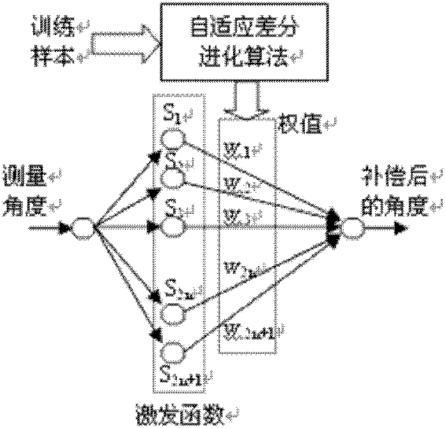
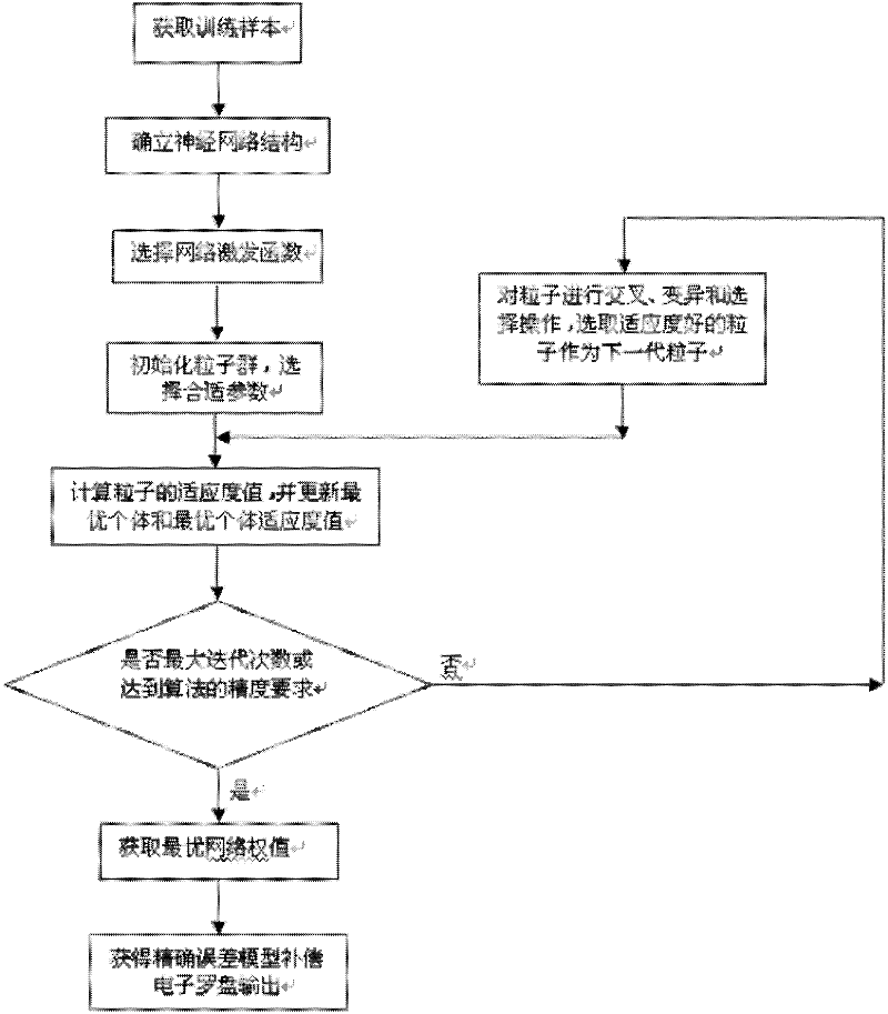
[0056] Attached below figure 1 The present invention is described further, the concrete realization steps of the present invention are:

[0057] Step 1: Obtain training samples: Rotate an ordinary two-dimensional solid-state magnetic resistance electronic compass with the manual turntable at a non-uniform speed in an indoor environment without any processing of the external magnetic field to obtain the measured value of the electronic compass and the corresponding The rotation angle of the turntable is used as a training sample, the measured value of the electronic compass is used as the value x to be compensated, and the rotation angle of the turntable is used as the ideal value Y.

[0058] The second step: determine the structure of the neural network: a single-input single-output Fourier neural network (SISO-FNN) is used to establish a model of the electronic compass direction angle error. The network is a three-layer forward network, and its three layers are input layer, ...


PUM


Abstract

The invention discloses a calibrating method for an electronic compass. The calibrating method is used for promoting measuring accuracy of the electronic compass based on a self-adaption differential evolution algorithm and a Fourier neural network theory and is especially suitable for an orienting system with low cost and higher precision. The calibrating method comprises the following steps: utilizing a Fourier neural network to perform error modeling on the electronic compass and utilizing an improved self-adaption differential evolution algorithm to optimize a weight value of the Fourier neural network, so as to acquire an accurate error model to compensate a measuring value of the electronic compass. The error model which is established according to the calibrating method is capable of realizing accurate mapping of a sample space and has a higher nonlinear approaching capability. According to the calibrating method, a minimum local part is avoided, the defects of over-slow convergence rate and oscillation of the neural network are overcome and the influence of an outside magnetic field on the electronic compass is efficiently compensated, thereby greatly promoting the measuring accuracy of the electronic compass.

Description

technical field [0001] The invention relates to a calibration method of an electronic compass, in particular to a calibration method of an electronic compass based on an adaptive differential evolution method and a Fourier neural network, and belongs to the field of directional navigation. Background technique [0002] Electronic compass is a device that realizes directional navigation function by measuring the earth's magnetic field. It is an important navigation tool that can provide the heading and attitude data of objects in real time, and has the advantages of small size, low cost, fast response speed, and no accumulation. It is widely used in the orientation subsystems of mobile robots, vehicles, aircrafts, etc.; however, since the electronic compass calculates the magnetic direction angle according to the principle of geomagnetism, other external magnetic fields other than the earth's magnetic field are inevitable in its working environment. It will affect the output ...

Claims


Application Information

Patent Timeline
Patent Type & Authority Patents(China)
IPC IPC(8): G01C17/38G06N3/08
Inventor 邓方陈杰龚鹍窦丽华
Owner BEIJING INSTITUTE OF TECHNOLOGYGY
Learn More