A squeeze roller for lead ingot cold granulator

A technology of cold granulator and extrusion roller, applied in the field of extrusion roller, which can solve the problems of long processing cycle, high difficulty, unfavorable maintenance and replacement of the roller body, etc., and achieve processing difficulty and cycle reduction, processing cycle and cost reduction , Conducive to the effect of maintenance and replacement

Inactive Publication Date: 2011-12-28
余华乔
View PDF7 Cites 5 Cited by
  • Summary
  • Abstract
  • Description
  • Claims
  • Application Information

AI Technical Summary

Problems solved by technology

[0003] The lead powder used in the manufacture of lead-acid batteries is to make granular lead lumps into powder through a lead powder machine. The traditional process for obtaining granular lead lumps is to melt the lead ingots in a lead melting furnace and cut them into granular shapes; The melting and cutting process not only wastes a lot of energy and produces a lot of waste of lead slag (lead oxide), but also seriously pollutes the environment
In this context, in 2008, Xi'an Qiyuan Electromechanical Equipment Co., Ltd. invented a cold granulator (CN 101306471B) that directly slices and rolls lead ingots into lead block particles in a cold state. The cold granulator can better solve the problems of energy waste and environmental pollution in the traditional process, but in the process of analyzing and implementing the disclosed cold granulator technology, it is found that the processing of the extrusion roller body is too difficult. The roller body is integrally processed and formed, mainly processed by electric pulses, which has the disadvantages of long processing cycle, high cost and high difficulty, and this kind of roller body is not conducive to maintenance and replacement. If the local convex knife or groove is damaged, Entire roller body needs to be replaced

Method used


Image

  • A squeeze roller for lead ingot cold granulator
  • A squeeze roller for lead ingot cold granulator
  • A squeeze roller for lead ingot cold granulator

Examples


Embodiment Construction

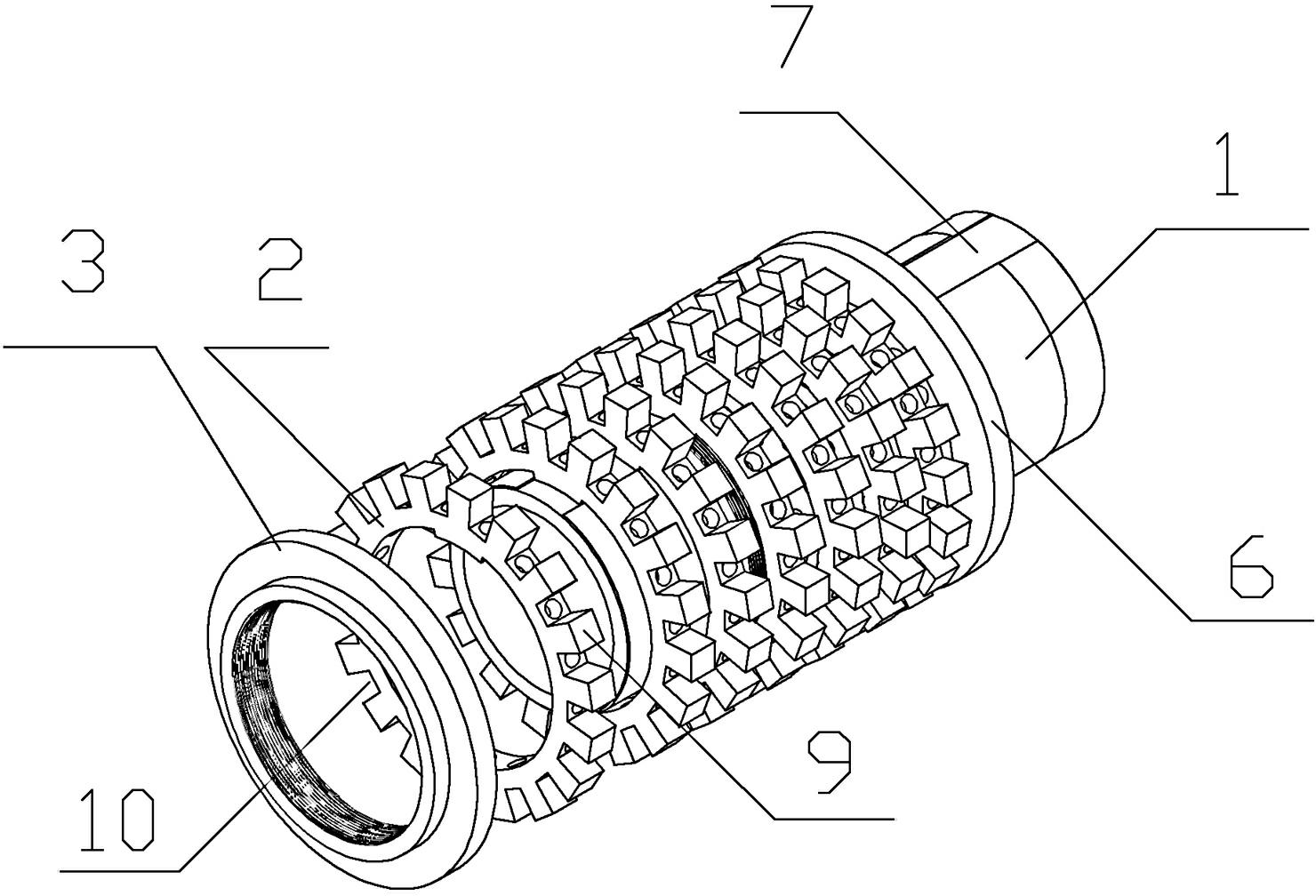
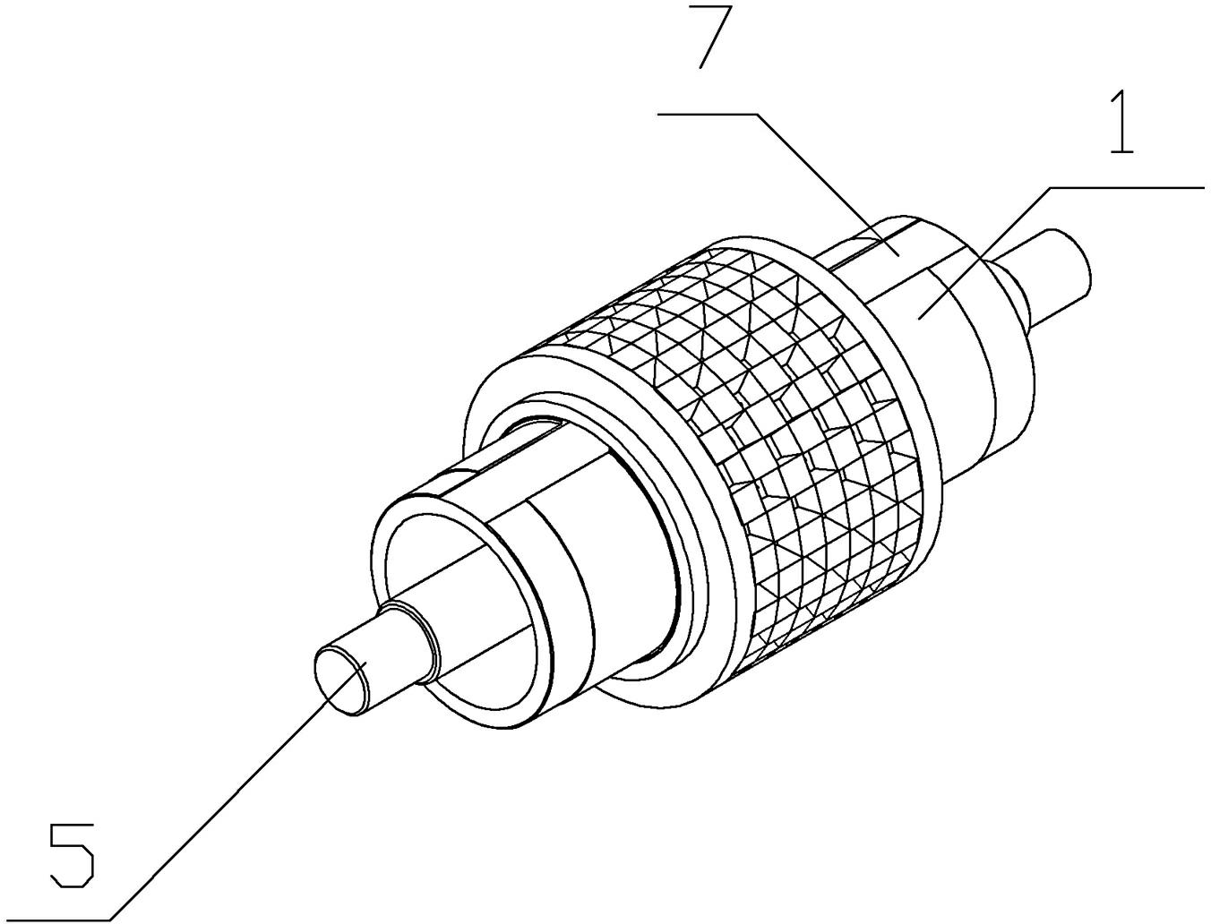
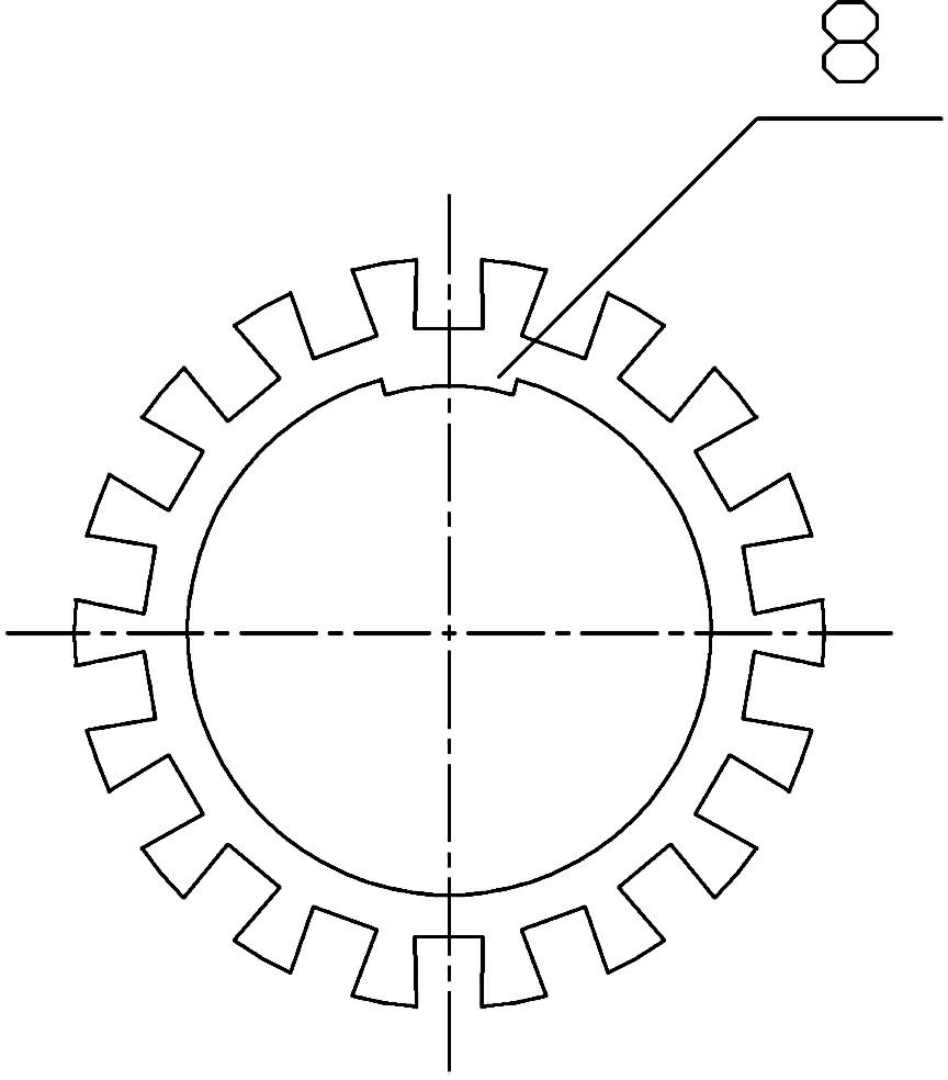
[0014] Such as figure 1 , figure 2 As shown, the extrusion roller of the present invention is assembled from a cavity main shaft 1, hob ring 2, lock nut 3, ejector rod 4 and eccentric ejector shaft 5, and 7 rows of separate hob rings 2 are set in the hollow On the outer peripheral surface of the cavity main shaft 1, a positioning plate 6 is provided on the cavity main shaft at the closed end of the hob ring 2 (that is, the end of the hob ring set on the cavity main shaft in the first row), which is useful for restricting and fixing the hob The closed end of the ring 2 and the open end of the hob ring (that is, the end of the hob ring set on the cavity main shaft in the last row) are fixed with the thread of the cavity main shaft 1 through the lock nut 3, and the axial surface of the cavity main shaft 1 There is a keyway 7 in the axial direction, combined with image 3 As shown, the inner ring of the hob ring 2 is provided with a flat key 8 matching the keyway 7, and the fla...


PUM


Abstract

The invention discloses an extruding roller for a lead ingot cold granulator. The roller body is set on the outer peripheral surface of the main shaft of the cavity. The bottom of the groove and the main shaft of the cavity corresponding to the bottom of the groove are provided with a through hole to form a hole for the ejector rod. The ejector rod is inserted from the groove bottom of the roller body and extends out of the hole for the ejector rod. The eccentric ejector shaft that pushes the ejector rod. The roller body is composed of hob rings arranged side by side. The circumferential direction of each row of hob rings is interlaced with convex knives and grooves. The bottom of the groove is provided with a through hole. The convex knives and grooves on the row of hob rings are arranged alternately. Each row of hob rings is sequentially set on the outer circumferential surface of the cavity main shaft. The cavity main shaft at the closed end of the hob ring is provided with a positioning plate for fixing the hob ring. The open end of the hob ring is fixed through the locking nut and the thread of the cavity main shaft. The hob ring in the present invention is simple to manufacture, low in cost, and convenient for maintenance and replacement.

Description

[0001] technical field [0002] The invention relates to the field of soft metal rolling granulation equipment, in particular to an extrusion roll used in a lead ingot cold granulator. Background technique [0003] The lead powder used in the manufacture of lead-acid batteries is to make granular lead lumps into powder through a lead powder machine. The traditional process for obtaining granular lead lumps is to melt the lead ingots in a lead melting furnace and cut them into granular shapes; The melting and cutting process not only wastes a lot of energy and produces a lot of waste of lead slag (lead oxide), but also seriously pollutes the environment. In this context, in 2008, Xi'an Qiyuan Electromechanical Equipment Co., Ltd. invented a cold granulator (CN 101306471B) that directly slices and rolls lead ingots into lead block particles in a cold state. The cold granulator can better solve the problems of energy waste and environmental pollution in the traditional process...

Claims


Application Information

Patent Timeline
IPC IPC(8): B22F9/04B01J2/22
CPCB30B11/16B30B15/32
Inventor 余华乔
Owner 余华乔
Why Eureka
Try Eureka