Refractory busway
A fire-resistant busway and fire-resistant technology, which is applied in the direction of open busway installation, etc., can solve the problems of inability to obtain heat insulation and fire resistance performance, fail to meet fire resistance performance requirements, and busway can not meet the current carrying capacity requirements, etc., to achieve good moisture-proof performance , good safety performance and excellent fire resistance
- Summary
- Abstract
- Description
- Claims
- Application Information
AI Technical Summary
Problems solved by technology
Method used
Image
Examples
Embodiment 1
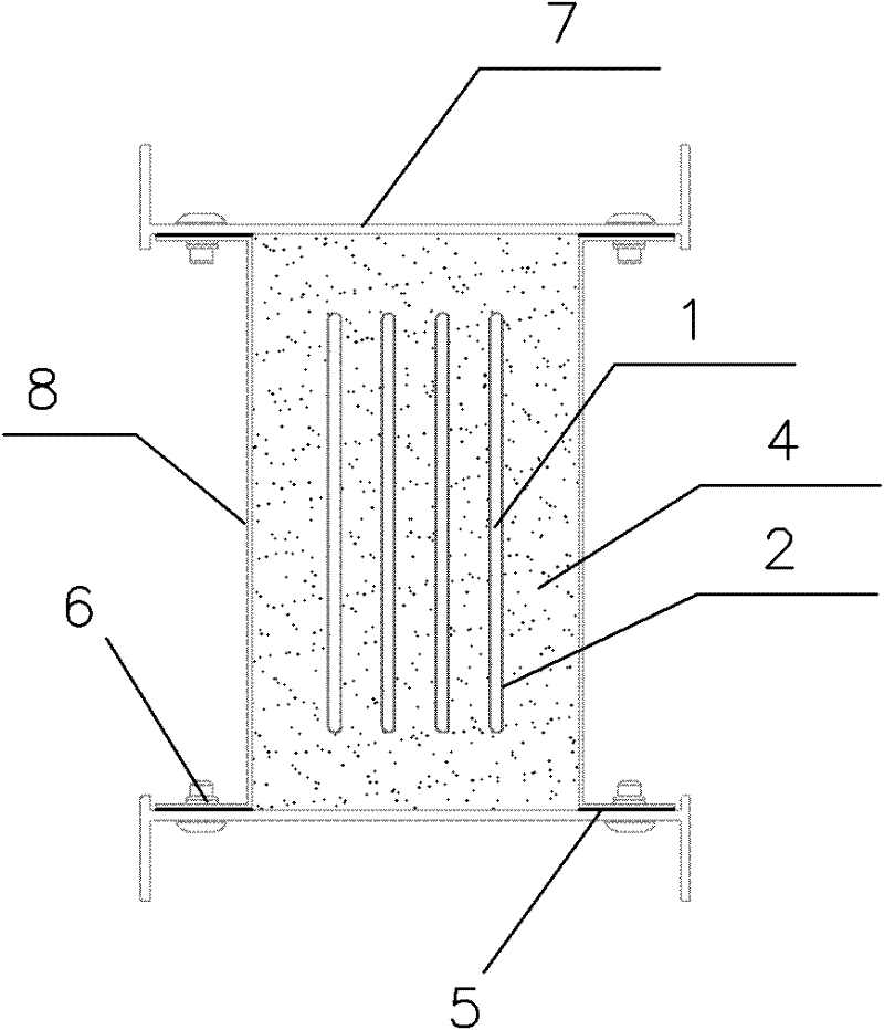
[0038] refer to Figure 1-4 , the fire-resistant busway of the present invention includes a cover plate 7 that closes the upper and lower ends of the busway, a side plate 8 that forms a metal shell of the busway together with the cover plate 7, and a conductor 1 arranged in the inner space of the metal shell. The layer 2 and the refractory filling 4, the conductor 1, the insulating layer 2 and the refractory filling 4 are integrally enclosed in a fully enclosed metal shell. In this embodiment, the cross-sectional shape of the metal shell is rectangular, and other shapes can be adopted as required.
[0039] The cover plate 7 and the side plate 8 are made of metal materials, such as steel plates or other alloy materials. In this embodiment, the side plate 8 is in the shape of “[”, and its two bent ends are respectively connected to the ends of the cover plate 7 through connecting pieces 6 . In this embodiment, bolts are used as the connecting pieces 6 . And a sealing strip 5 i...
Embodiment 2
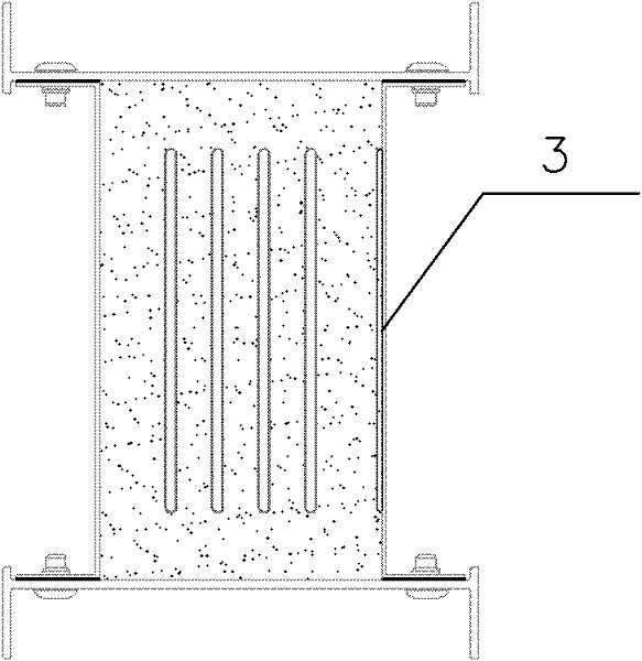
[0045] Such as Figure 5-12 As shown, as other solutions of the present invention, the other parts of embodiment 2 are the same as embodiment 1, except that:
[0046] The conductor 1 adopts profiles with irregular shapes or bent shapes to meet different application requirements.
Embodiment 3
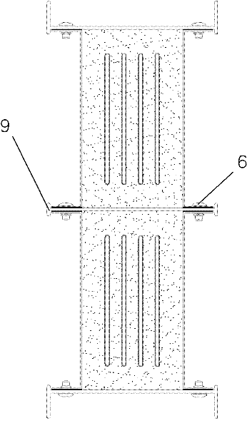
[0048] Figure 13-14 Shown is the exploded diagram of the device adopting the refractory busway of the present invention, Figure 14 A double-row busway arrangement formed by parallel joining of single-row busway arrangements is shown. The bus duct device of the present invention includes two adjacent dense bus ducts 200 and a connector 100 connecting the two bus ducts 200 together, wherein the bus duct 200 is used to install a group of mutually insulated conductors such as conductive copper Row. After the exterior of each conductor is coated with an insulating layer, the multi-phase is sealed and compressed in a bus duct 200 .
[0049] Wherein, the connecting head 100 includes connecting side plates 10 arranged on the front and rear sides respectively, connecting cover plates 13 combined and connected with the upper and lower ends of the connecting side plates 10 , and being arranged on a wall surrounded by the connecting side plates 10 and the connecting cover plates 13. ...
PUM
 Abstract
Description
Claims
Application Information
 - R&D
- Intellectual Property
- Life Sciences
- Materials
- Tech Scout
- Unparalleled Data Quality
- Higher Quality Content
- 60% Fewer Hallucinations
Browse by: Latest US Patents, China's latest patents, Technical Efficacy Thesaurus, Application Domain, Technology Topic, Popular Technical Reports.
© 2025 PatSnap. All rights reserved.Legal|Privacy policy|Modern Slavery Act Transparency Statement|Sitemap|About US| Contact US: help@patsnap.com


