Heat transfer tube and heat exchanger with inner surface groove
A heat transfer tube, inner surface technology, applied in heat exchange equipment, tubular elements, lighting and heating equipment, etc., can solve problems such as the reduction of heat exchange performance of heat exchangers, reduce fin crushing, ensure heat exchange performance, The effect of stabilizing heat transfer performance
- Summary
- Abstract
- Description
- Claims
- Application Information
AI Technical Summary
Problems solved by technology
Method used
Image
Examples
no. 1 approach
[0032] The overall structure of the heat transfer tube
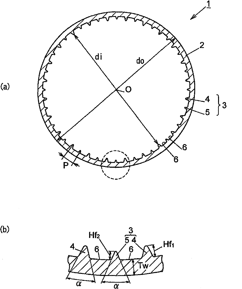
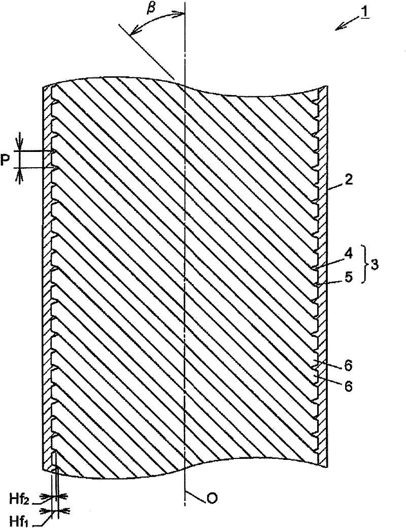
[0033] in figure 1 and figure 2 Here, the reference numeral 1 indicating the entirety schematically indicates the typical heat transfer tube with an inner groove of the first embodiment. The heat transfer tube 1 is made of a copper-based material such as copper or copper alloy, or an aluminum-based material such as aluminum or aluminum alloy, and has a tube main body 2 formed of a round tube.
[0034] Such as figure 1 and figure 2 As shown, the inner surface of the tube main body 2 is formed with a plurality of fins 3,..., 3 helically processed in the tube axis O direction (tube length direction). The pipe main body 2 of the illustrated example has an outer diameter do of 6.35 mm and a minimum inner diameter di of 5.61 mm. The groove bottom thickness Tw of the portion of the pipe main body 2 where the fin 3 is not present is set to 0.22 mm.
[0035] The internal structure of the heat transfer tube
[0036] The fin 3 of the h...
no. 2 approach
[0052] Heat Exchanger
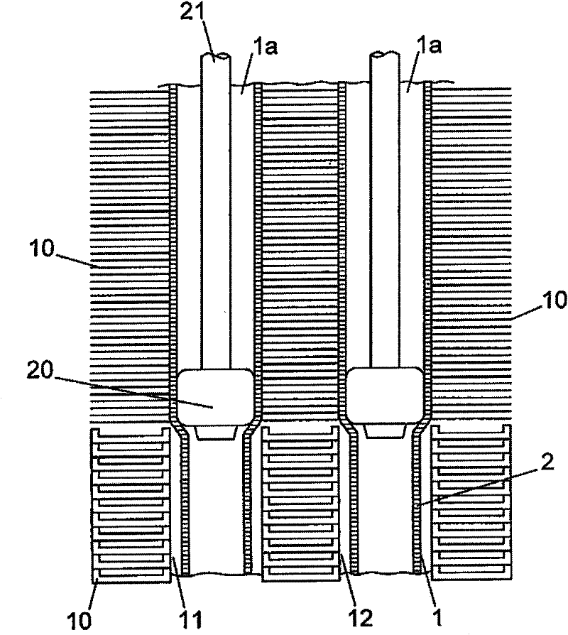
[0053] Reference image 3 , image 3 The outline of fabricating a heat exchanger using the heat transfer tube 1 formed as described above is illustrated as an example. According to the figure, the aluminum thin plate-shaped fins 10 are arranged in parallel, punched and punched to have a through hole 11 with a diameter larger than the outer diameter of the heat transfer tube 1, and inserted into the tube according to a conventional method through the through hole 11 The surface of the heat transfer tube 1 is formed by roll forming and bending into a U-shape. At this time, a gap 12 is formed between the outer surface of the heat transfer tube 1 and the through hole 11 of the thin plate-shaped fin 10.
[0054] The tube expansion mandrel 20 is inserted into the heat transfer tube 1 along the tube length direction of the heat transfer tube 1 by pressing the rod 21, and the heat transfer tube 1a is expanded to form the tube expansion heat transfer tube 1a, and th...
Embodiment
[0063] Hereinafter, as more specific embodiments of the present invention, examples and comparative examples are given, and reference is made to Figure 4 ~ Figure 6 And Table 1 to Table 6, the heat transfer tube with inner groove is described in detail. In addition, in this embodiment, a typical example of a heat transfer tube with an inner groove is given, but the present invention is of course not limited to these embodiments.
[0064] Dimensions of heat transfer tube with internal groove
[0065] Using the original copper tube, the inner surface of the tube was roll-formed according to the conventional method. The fin height difference was 0.01mm, the fin height difference was 0.02mm, and the fin height difference was 0.03 under the size conditions shown in Table 1 below. 4 kinds of heat transfer tubes with a fixed height of mm and fins. As shown in Table 1 below, the average outer diameter, minimum inner diameter, bottom thickness, number of grooves, fin top angle, spiral an...
PUM
 Abstract
Description
Claims
Application Information
 - R&D
- Intellectual Property
- Life Sciences
- Materials
- Tech Scout
- Unparalleled Data Quality
- Higher Quality Content
- 60% Fewer Hallucinations
Browse by: Latest US Patents, China's latest patents, Technical Efficacy Thesaurus, Application Domain, Technology Topic, Popular Technical Reports.
© 2025 PatSnap. All rights reserved.Legal|Privacy policy|Modern Slavery Act Transparency Statement|Sitemap|About US| Contact US: help@patsnap.com


