


Quick Research
Generate reliable direction feasibility study reports for your R&D in just a few steps.

Technical Q&A
Discover and master advanced knowledge NOW. Basics, ideas, possibilities, all at once.

Find Solutions
As an expert in R&D theories, this can generate solutions to your technical problems instantly.

Evaluate Feasibility
Analyze your overall solution with one click, know your potential R&D risks in advance.

Monitor Landscape
Get weekly tech updates, stay abreast of the latest tech innovations and key insights.
A dual-band high-temperature superconducting filter
A dual-passband filter, high-temperature superconducting technology, applied in the field of filters, can solve the problems of complex structure, large volume, difficult matching and debugging, etc., and achieve the effect of compact structure, flexible design and small volume
- Summary
- Abstract
- Description
- Claims
- Application Information
AI Technical Summary
Problems solved by technology
Method used
Image

Examples
Embodiment 1
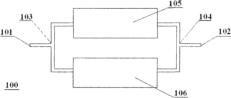
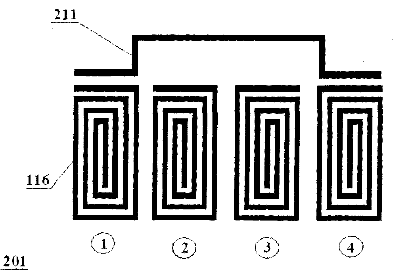
[0024] Embodiment 1: A kind of high-temperature superconducting double-pass band filter 300, comprises three parts of microstrip resonator array 303, input microstrip 301, output microstrip 302, is characterized in that through the microstrip resonator array 303 Cross-coupling 211 and 212 are introduced between non-adjacent resonators 116 ① and ④ and between ⑤ and ⑧ to realize the filtering characteristics of dual passbands 511 and 512 .
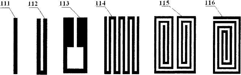
[0025] The above-mentioned microstrip resonator array 303 of the high-temperature superconducting double-passband filter 300 has a structure of the resonator 116 that is a half-wavelength resonator, and the shape of the resonator is a spiral type. The number is 8.
[0026] In the above-mentioned microstrip resonator array 303 of the HTS dual passband filter 300 , the resonant frequency of the resonators 116 is higher than the center frequency of the low frequency passband 511 and lower than the center frequency of the high frequency passband...
Embodiment 2
[0033] Embodiment 2: A high-temperature superconducting double-pass band filter 400, including a microstrip resonator array 403, an input microstrip 401, and an output microstrip 402. It is characterized in that through the microstrip resonator array 403 Cross-coupling is introduced between the non-adjacent resonators 116 ②, ⑤ to realize the filter characteristic of double passband.
[0034] The number of resonators 116 in the microstrip resonator array 403 of the above-mentioned high-temperature superconducting double-passband filter 400 is six.
[0035] The microstrip resonator array 403 of the above-mentioned high-temperature superconducting double-passband filter 400 has four adjacent resonators 116②,③,④,⑤ forming a group, and the first ② and the last resonator ⑤ Introduce a cross-coupling between.
[0036] Cross-coupling is introduced between the non-adjacent resonators 116 ② and ⑤ of the above-mentioned high-temperature superconducting double-passband filter 400 , and t...
PUM
 Abstract
Description
Claims
Application Information
 - R&D Engineer
- R&D Manager
- IP Professional
- Industry Leading Data Capabilities
- Powerful AI technology
- Patent DNA Extraction
Browse by: Latest US Patents, China's latest patents, Technical Efficacy Thesaurus, Application Domain, Technology Topic, Popular Technical Reports.
© 2024 PatSnap. All rights reserved.Legal|Privacy policy|Modern Slavery Act Transparency Statement|Sitemap|About US| Contact US: help@patsnap.com