
Stamping die and stamping method for hard metal alloy cutting blades

A technology of cemented carbide blades and stamping dies, which is applied to knives, kitchen utensils, household utensils, etc. It can solve the problems of lengthening the processing cycle and production cost, difficult molding, and complicated mold making, so as to improve the first pass rate and improve production. Efficiency and the effect of speeding up the production cycle

Active Publication Date: 2013-07-17
江西江钨硬质合金有限公司
View PDF4 Cites 0 Cited by
  • Summary
  • Abstract
  • Description
  • Claims
  • Application Information

AI Technical Summary

Problems solved by technology

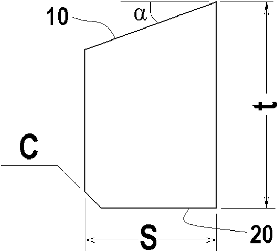
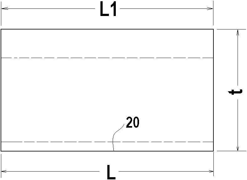
Therefore, during the pressing production of the product blank, it is difficult to ensure that the density of the product working surface 10 is uniform, and the compact density of the produced product working surface 10 is less than the compact density of the welding surface 20. After high-temperature sintering, the size of the working surface 10 The shrinkage of the size of the welding surface 20 is larger, resulting in inconsistency in the length of the product. The welding surface 20 can be 0.3-0.6mm larger than the working surface 10, which reduces the first pass rate of the product
[0006] Therefore, the traditional mold design scheme is difficult to control the length and size of the product during production, and the production of this mold is relatively complicated. It needs to go through two processes of wire cutting and then EDM drilling, which virtually lengthens the processing cycle and production. cost
Its geometric shape makes it difficult to form and the mold making is complicated. Therefore, it is necessary to change its original mold design

Method used


Image

  • Stamping die and stamping method for hard metal alloy cutting blades
  • Stamping die and stamping method for hard metal alloy cutting blades
  • Stamping die and stamping method for hard metal alloy cutting blades

Examples


Embodiment Construction

[0022] The present invention will be further described below in conjunction with accompanying drawing:

[0023] Such as Figure 1A with 1B As shown, in an ideal state, the length dimension of the welding surface 20 of the product is L; in an ideal state, the length dimension of the product working surface 10 is L1; the value of L1 is close to the value of L; the width dimension of the product is t; the thickness dimension of the product is S .

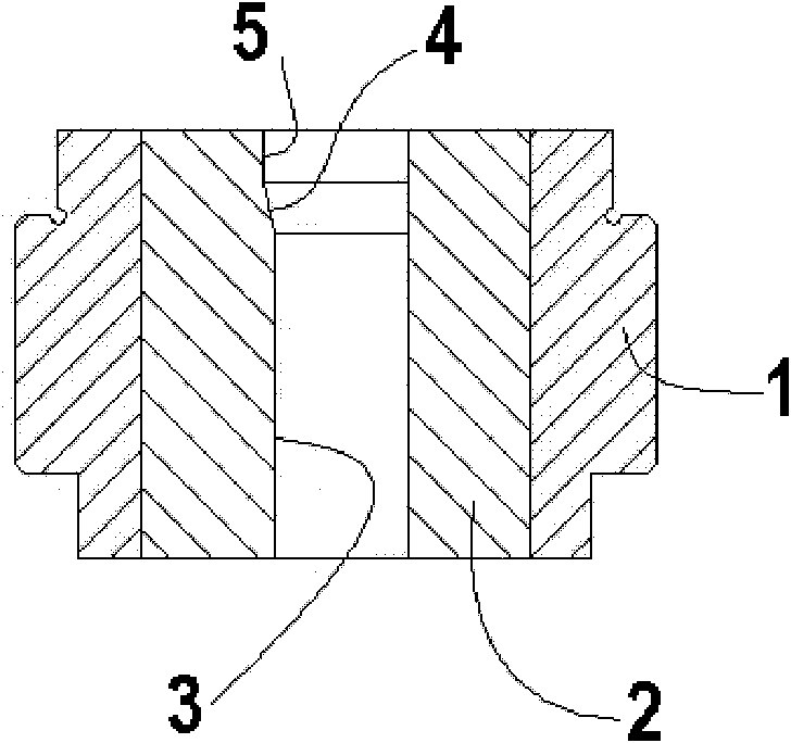
[0024] Such as Figure 3A with 3B As shown, the mold according to the D2 type product of the present invention includes a steel sleeve 1 as a mold body and an alloy mold core 2 embedded in the steel sleeve 1 . The center of the alloy mold core 2 is a die hole 3 with a constant cross section from top to bottom. The die hole 3 is formed by wire cutting; the product blank forming area is used as a part of the die hole 3, and the slope corresponding to the product working surface 10 is canceled, and EDM is no longer required as the sec...


PUM

PropertyMeasurementUnit
shrinkage factoraaaaaaaaaa

Abstract

The invention relates to a stamping die for hard metal alloy cutting blades. The stamping die is characterized in that a die hole (3) is rectangular, the longitudinal size of the die hole (3) corresponds to the length (L) of a blank (50), the transversal size corresponds to the thickness (S) of the blank (50), and the stamping height corresponds to the width (t) of the blank (50); a working surface (10) of the blank (50) is formed upwards; the cross section of the die hole (3) is constant; the lower surface of an upper stamping head (101) of an upper die (100) is an inclined surface capable of being tightly attached to the working surface (10), and the cross section of a chamfered bulge corresponds to the blank (50) is arranged on the upper surface of a lower stamping head (201) of a lower die (200). According to the stamping die provided by the invention, the primary percent of pass of products is improved; the unit weight of a manufactured qualified product is 0.5-2g lighter than that of the product of the prior art, therefore a great amount of resources can be saved; and the manufacturing cycle of the dies is accelerated, the processing cost of the dies is reduced, and the production efficiency is improved.

Description

technical field [0001] The invention relates to a stamping die and a stamping method of a cemented carbide blade, in particular to a stamping die and a stamping method of a cemented carbide blade similar to a D2 product shape. Background technique [0002] D2 type products are mainly used to manufacture side and side milling cutters, T-slot milling cutters and floating boring cutters, etc., and are widely used in industry. Such as Figure 1A with Figure 1B As shown, the cross-section of the D2-type product is generally a right-angled trapezoid. The bottom of the trapezoid, that is, the width of the product is t; the height of the trapezoid, that is, the thickness of the product is S; the hypotenuse of the trapezoid, that is, it The working surface 10 has a relief angle α of 14°, and a chamfer C of 0.8×45° is arranged between the welding surface 20 and the right-angled side of the trapezoid. In an ideal state, the length dimension of the welding surface 20 of the product i...

Claims


Application Information

Patent Timeline
Patent Type & Authority Patents(China)
IPC IPC(8): B21D37/10B21D53/64
Inventor 欧立明周则明陈辉史太平朱早生严武华
Owner 江西江钨硬质合金有限公司
Learn More