
A spray cooling nozzle for grinding

A technology for spray cooling and grinding processing, which is applied in metal processing equipment, grinding/polishing equipment, grinding/polishing safety devices, etc. It can solve the problems of low spray jet velocity, poor atomization effect, and complex nozzle structure. Achieve the effects of prolonged contact time, increased contact area, and long contact time

Inactive Publication Date: 2011-12-14
CHANGSHA UNIVERSITY OF SCIENCE AND TECHNOLOGY
View PDF6 Cites 12 Cited by
  • Summary
  • Abstract
  • Description
  • Claims
  • Application Information

AI Technical Summary

Problems solved by technology

Among them, the internal mixing nozzle means that the gas and grinding fluid are mixed in the atomization chamber of the nozzle, and then expanded and sprayed from the nozzle. The disadvantage of this structure is that the spray jet velocity is low, and at the same time, the grinding fluid is The axial direction enters the atomization chamber and is in the "leeward" of the high-pressure gas, so the atomization effect is poor
The external mixing nozzle refers to the external mixing of gas and grinding fluid at the nozzle nozzle. Although this structure has a certain spray jet velocity, the atomization effect is not ideal due to the short contact time between the gas and the grinding fluid.
The Y-type nozzle is a combination of internal mixing and external mixing. This type of nozzle has a complex structure and is only suitable for atomization of high-viscosity solutions and pasty media.

Method used


Image

  • A spray cooling nozzle for grinding
  • A spray cooling nozzle for grinding
  • A spray cooling nozzle for grinding

Examples


Embodiment Construction

[0029] The present invention will be further described below in conjunction with the accompanying drawings and specific embodiments.

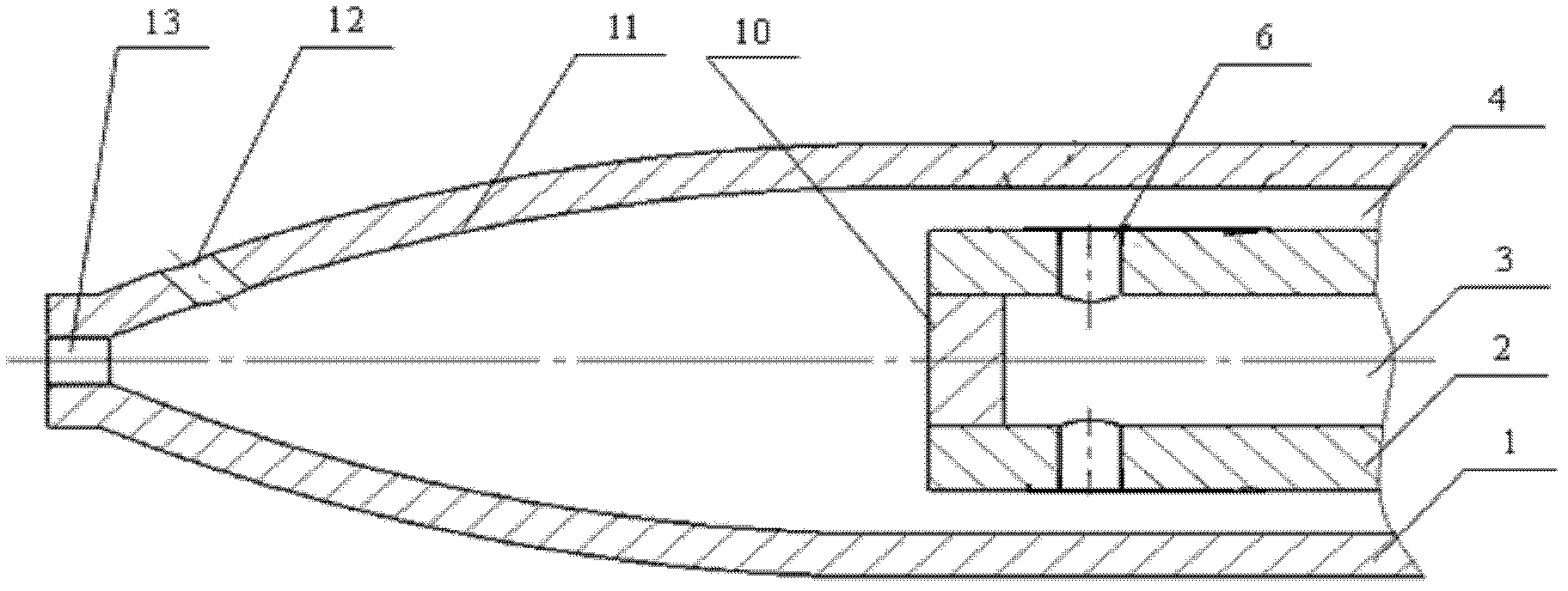
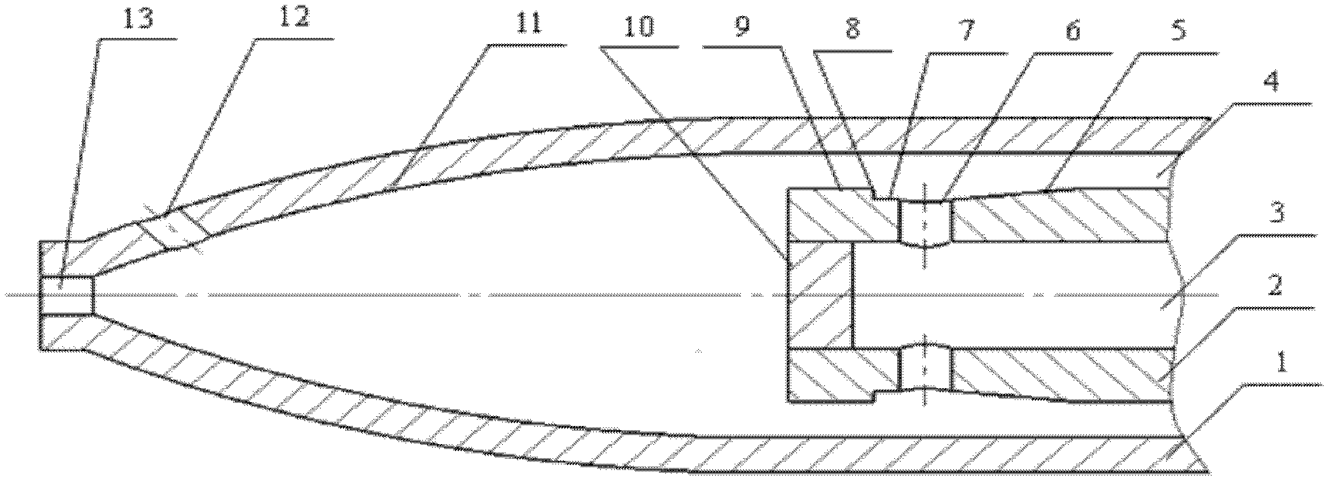
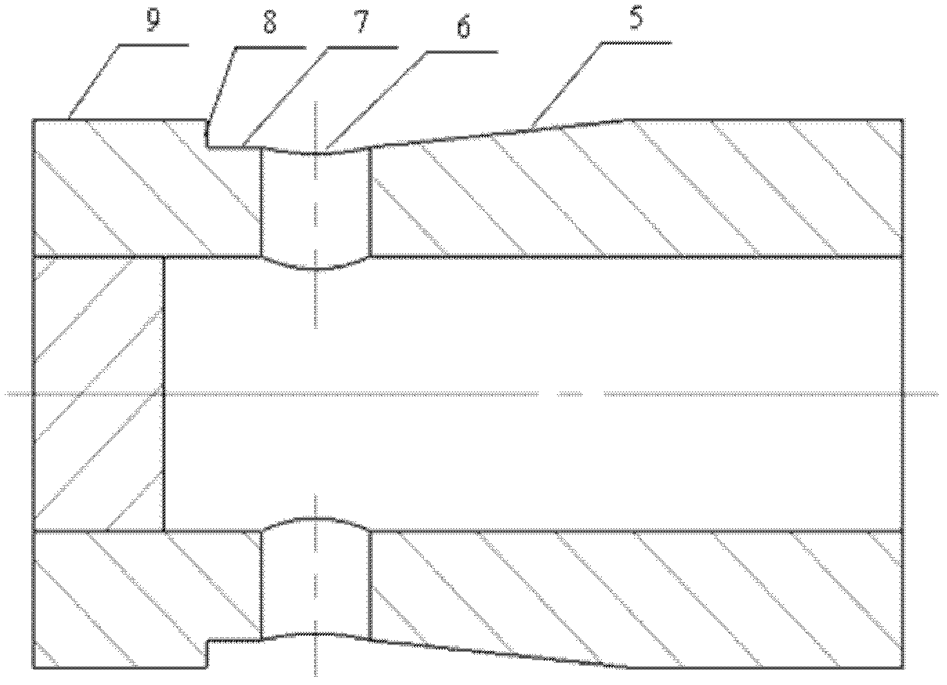
[0030] see figure 1 , the grinding liquid pipe 2 with a smaller diameter is installed in the air pipe 1 with a larger diameter, the axes of the two pipes coincide, and the high-pressure gas enters the air pipe 1 under the action of the external gas supply system, and the gap between the two pipes is High pressure gas channel 4. The grinding fluid enters the grinding fluid pipe 2 under the action of the external liquid supply device, and the inner hole of the grinding fluid pipe 2 is the grinding fluid channel 3 . Close one end of the grinding fluid pipe 2 with an end-sealing plate 10, and radially evenly open 4 to 6 radial liquid outlet holes 6 with a diameter of 1 to 1.5 mm near the end-sealing plate 10, and from the other end of the grinding fluid pipe 2 After the grinding fluid injected at one end passes through the grinding fluid channel ...


PUM

PropertyMeasurementUnit
Lengthaaaaaaaaaa

Abstract

The invention discloses a spray cooling nozzle for grinding processing. The end face of the grinding liquid pipe (2) is closed, and the end face adjacent to the grinding liquid pipe (2) is evenly provided with a plurality of radial liquid outlet holes along the circumferential direction. (6). The externally injected grinding fluid and the high-pressure gas in the gas pipe are mixed on the outside of the grinding fluid pipe, the liquid droplets ejected from the radial outlet holes are on the windward side, and the flow rate of the grinding fluid in a single radial outlet hole is far The flow rate of the grinding liquid pipe is smaller than that of the grinding liquid pipe, which makes the grinding liquid droplets break up into micron-sized and evenly distributed mist droplets. Spray into the grinding area along the nozzle and maintain a high spray jet velocity to lubricate and cool the grinding area. The invention has the advantages of long gas and liquid contact time, good atomization effect, small diameter and uniform distribution of droplets, high jet velocity, simple manufacturing process and the like, and is suitable for a spray cooling system for grinding processing.

Description

technical field [0001] The invention relates to a nozzle, in particular to a nozzle suitable for spray cooling for grinding. Background technique [0002] During the grinding process, the spray cooling method is often used to lubricate and cool the grinding area to reduce the generation of grinding heat and take away the generated heat in time. Among them, the structure of the nozzle will have a great influence on the mixing method of gas and grinding fluid, atomization effect, droplet diameter and distribution uniformity, spray jet velocity, etc., thus determining the grinding area to a large extent. Therefore, when designing the structure of the nozzle, the key technical problem is to make the contact between the grinding fluid and the high-pressure gas in the best state during atomization, so as to ensure that it has good atomization effect and high spray jet velocity. At present, the structure of the nozzle can usually be divided into internal mixing type, external mix...

Claims


Application Information

Patent Timeline
IPC IPC(8): B05B7/04B05B15/00B24B55/02
Inventor 毛聪汤小君邹洪富周志雄张志勇张健胡宏伟邵毅敏
Owner CHANGSHA UNIVERSITY OF SCIENCE AND TECHNOLOGY
Learn More