Dustproof frost-proof optical telescope system in direct contact with atmosphere

A telescope and direct technology, applied in the field of laser and remote sensing, can solve the problems of doubling the manufacturing cost of lidar systems, affecting the receiving efficiency of optical telescopes, and high requirements for optical protective lenses, achieving compact structure, improving detection efficiency, and good shock resistance.

Inactive Publication Date: 2013-01-09
UNIV OF SCI & TECH OF CHINA
View PDF0 Cites 0 Cited by
  • Summary
  • Abstract
  • Description
  • Claims
  • Application Information

AI Technical Summary

Problems solved by technology

[0005] The current method of adding protective lenses has the following defects: First, because the requirements for optical protective lenses are also very high, this will double the manufacturing cost of the entire lidar system
Second, for large-aperture optical telescopes, the primary mirror can be installed without deformation, but the optical protective lens needs to be installed on the barrel mouth of the telescope, and it is difficult to control the influence of deformation on the wavefront, thereby affecting the receiving efficiency of the optical telescope
Third, the larger the caliber of the optical telescope, the larger the caliber and the greater the quality of the optical protective lens. Not only is it inconvenient to disassemble, but it is also inconvenient to clean. hurt
Fourth, in frosty weather or in the early morning, frost or condensation dew is easy to form on the surface of the protective lens, and the water droplets will dissolve the soluble matter in the dust, forming a "salt bridge" between the dust particles and the glass surface, increasing the difficulty of dust removal. Moreover, the water itself may also dissolve a small amount of harmful substances, causing slight erosion to the glass surface.
Fifth, even installing protective lenses does not necessarily guarantee that the surface of the telescope is free from dust

Method used


Image

  • Dustproof frost-proof optical telescope system in direct contact with atmosphere
  • Dustproof frost-proof optical telescope system in direct contact with atmosphere
  • Dustproof frost-proof optical telescope system in direct contact with atmosphere

Examples


Embodiment Construction

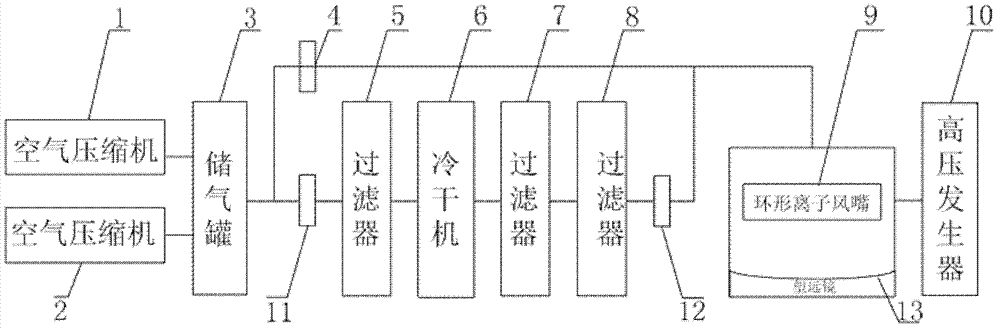
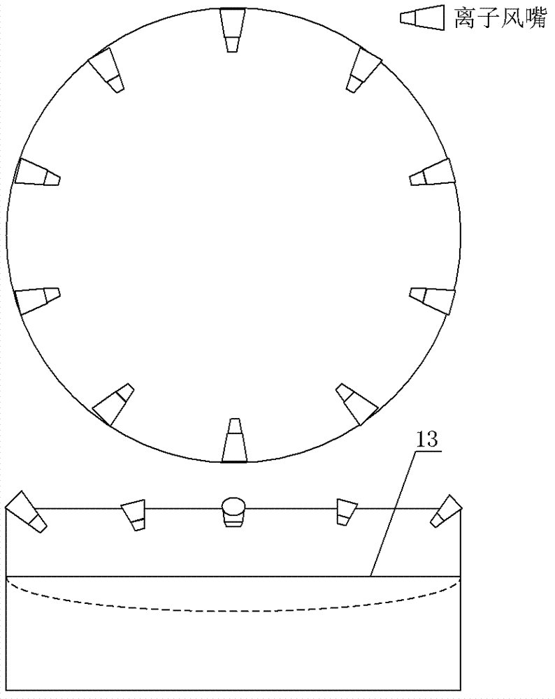
[0021] Such as figure 1 As shown, the present invention includes a telescope 13, an annular ion tuyere 9, a high-voltage generator 10 and a cleaning and drying device. Ring-shaped ion tuyere 9 is respectively installed in several symmetrical directions above the bucket of telescope 13, and high-voltage generator 10 is connected with annular ion tuyere 9, and the high-pressure airflow passing through annular ion tuyere 9 is ionized by high-voltage generator 10 to generate a large amount of Positive and negative ions are blown toward the telescope 13 quickly along the barrel wall of the telescope along with the airflow, close to the curved surface of the telescope 13, and concentrate in the center of the telescope 13, finally forming a uniform, stable upward airflow. The dry clean air generated by the clean drying device is used as the ionized gas of the ring-shaped ion air nozzle.

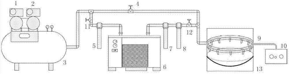
[0022] Such as figure 2 As shown, the clean drying device of the embodiment of the present i...


PUM


Abstract

The invention discloses a dustproof frost-proof optical telescope system in direct contact with atmosphere. The telescope system comprises a telescope, annular ion tuyeres, a high-pressure generator and a cleaning drying device; the annular ion tuyeres are respectively arranged in a plurality of symmetric directions above a barrel of the telescope, the high-pressure generator is connected with the annular ion tuyeres, the high-pressure airflow passing through the annular ion tuyeres is ionized through the high-pressure generator to generate a large amount of positive and negative ions which are rapidly blown to the telescope together with the airflow along the barrel wall of the telescope, the positive and negative ions are close to an arc surface of the telescope and concentrated on the centre of the telescope to finally form uniform and steady upward airflow; the dry and clean air generated by the cleaning drying device is used as ionization air of the annular ion tuyeres. The telescope can work directly in the air; therefore, the detection efficiency of the telescope is improved, weak vibration is resisted, and the adaptability of the optical laser radar in a special weather condition is improved.

Description

technical field [0001] The invention relates to an optical telescope system, in particular to a dust-proof and frost-proof optical telescope system directly in contact with the atmosphere, which is mainly used in the fields of laser and remote sensing. Background technique [0002] Lidar is a radar system that emits laser beams to detect the position, speed and other characteristics of the target. It transmits a detection signal (laser beam) to the target, and then combines the received signal reflected from the target (target echo) with the transmitted signal. After comparison, after proper processing, the relevant information of the target can be obtained, such as target distance, orientation, height, speed, attitude, and even shape and other parameters. [0003] The optical telescope is mainly used to receive the echo signal emitted by the lidar and scattered by the target object, and focus it into the receiving optical system. Therefore, the larger the aperture of the te...

Claims


Application Information

Patent Timeline
Patent Type & Authority Patents(China)
IPC IPC(8): G02B23/00G01S7/481
Inventor 窦贤康孙东松王晶晶夏海云舒志峰胡冬冬薛向辉陈廷娣
Owner UNIV OF SCI & TECH OF CHINA
Why Eureka
Try Eureka