
Precise type dynamic and static pressure ceramic main shaft device

A dynamic and static pressure, ceramic technology, used in metal processing machinery parts, maintenance and safety accessories, metal processing equipment and other directions, can solve the problems of difficult processing of ceramic parts, fragile edges of ceramic parts, leakage of lubricants, etc., and achieve small thermal deformation. , avoid shape mutation, improve the effect of wear resistance

Inactive Publication Date: 2013-06-19
TIANJIN UNIV
View PDF0 Cites 0 Cited by
  • Summary
  • Abstract
  • Description
  • Claims
  • Application Information

AI Technical Summary

Problems solved by technology

[0006] The purpose of the present invention is to solve the problems existing in the existing dynamic and static pressure ceramic spindle devices, such as fragile edges of ceramic parts, easy breakage at sudden changes in the shape of ceramic parts, difficult processing of ceramic parts, high rejection rate and serious leakage of lubricating fluid, etc., and provides a precision dynamic and static The ceramic device for pressing the main shaft can protect the edge of the ceramic part and improve its impact resistance; improve the strength of the radial-thrust joint bearing; improve the machinability of the ceramic part and increase the yield; improve the sealing performance of the main shaft

Method used


Image

  • Precise type dynamic and static pressure ceramic main shaft device
  • Precise type dynamic and static pressure ceramic main shaft device
  • Precise type dynamic and static pressure ceramic main shaft device

Examples


Embodiment Construction

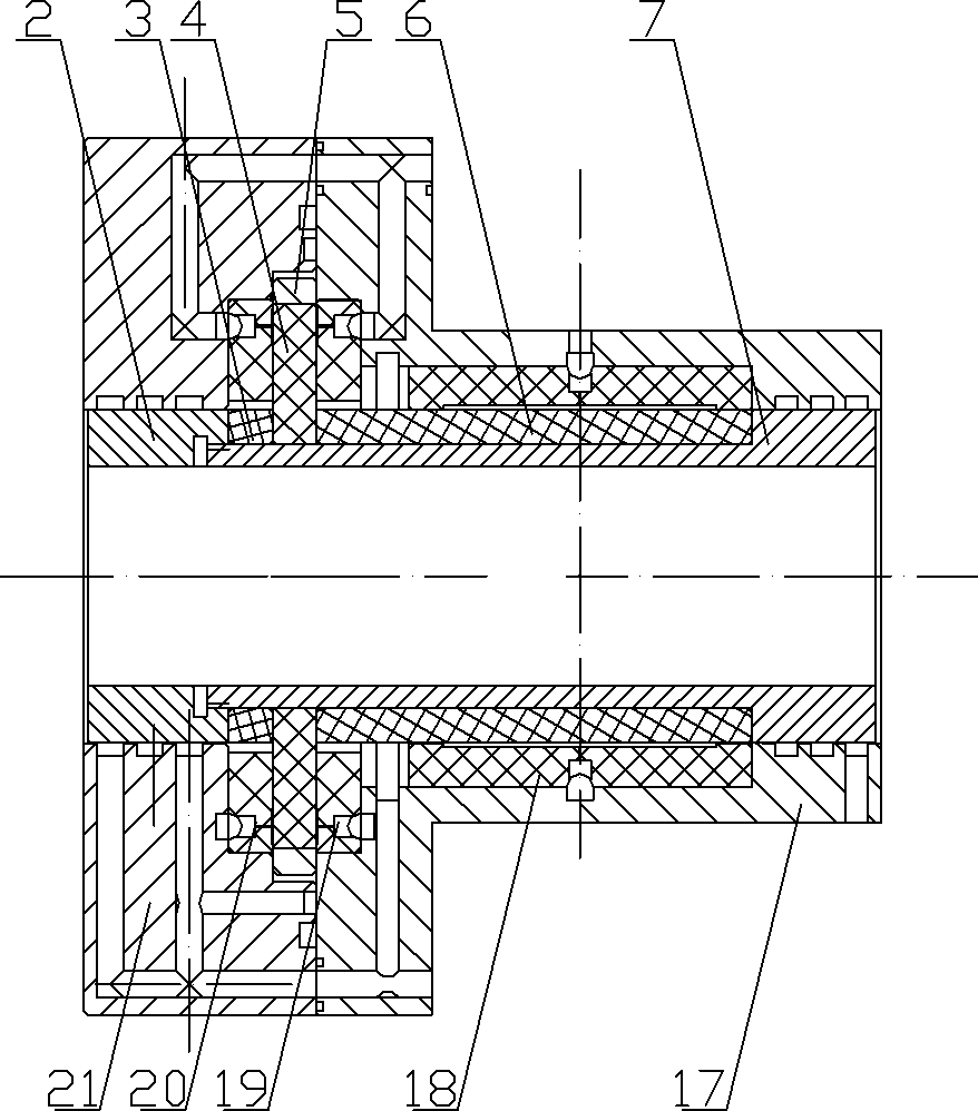
[0099] Aiming at the problems of high temperature rise and low bearing capacity of water-lubricated spindles at high speeds for ordinary oil-lubricated spindles, the present invention proposes a precision dynamic and static pressure ceramic spindle device, wherein the lubricant of the spindle is water-based lubricating fluid. In order to solve the problems of poor wear resistance and high thermal expansion coefficient of the traditional spindle-bearing metal friction pair, and to adapt to the state where boundary friction and dry friction are prone to occur in the low-viscosity lubrication of water-based lubricating fluid, the material of the spindle-bearing friction pair in the present invention for ceramic materials. The existing ceramic sliding bearing structure is too simple to meet the working needs of the main shaft, and the ceramic parts are prone to stress concentration. In the design of the main shaft structure in the present invention, ceramic dynamic and static beari...


PUM


Abstract

The invention discloses a precise type dynamic and static pressure ceramic main shaft device. A front radial-bidirectional thrust bearing is mounted at the front end of a main shaft, and a back radial bearing is mounted at the back end of the main shaft. The front radial-bidirectional thrust bearing comprises a front main shaft lining. A front ceramic right shaft sleeve, a thrust ceramic shaft sleeve, a front ceramic left shaft sleeve and a front shaft sleeve end cover are assembled at the external part of the front main shaft lining. A thrust shaft sleeve lining is assembled at the externalpart of the thrust ceramic shaft sleeve. A radial ceramic bearing bush, a left thrust ceramic bearing brush, a right thrust ceramic bearing brush, a front bearing brush lining and a front bearing brush end cover are mounted on a stand. The back radial bearing comprises a back main shaft lining. A back ceramic shaft sleeve and a back shaft sleeve end cover are assembled on the back main shaft lining. A back bearing brush end cover, a back ceramic bearing brush and a back bearing brush lining are mounted on the stand. The edge of a ceramic part can be protected by the precise type dynamic and static pressure ceramic main shaft device, so that the impact resistance is enhanced; the strength of a radial-thrust combined bearing is enhanced; the processibility of the ceramic part is enhanced, and the finished product ratio is increased; and the sealing property of the main shaft is enhanced.

Description

technical field [0001] The invention relates to a mechanical assembly part, in particular to a dynamic and static pressure spindle device. Background technique [0002] CNC machine tools are developing in the direction of ultra-high speed and ultra-precision. As the core component of CNC machine tools, the machine tool spindle determines the performance level of the machine tool. In the current high-speed spindle bearing technology, the large vibration and noise of rolling bearings, the overly complicated control system of magnetic bearings and the low load-carrying capacity of gas bearings limit its further development. The hydrodynamic and static pressure support method is widely used in the field of high-speed precision machine tools because of its excellent high-speed performance, high vibration damping, high rotation accuracy, high stiffness, small damping and long life. [0003] The main problems of the traditional hydrodynamic and static pressure spindle are: the tem...

Claims


Application Information

Patent Timeline
Patent Type & Authority Patents(China)
IPC IPC(8): B23B19/02B23Q11/12
Inventor 林彬刘峰闫帅刘文龙
Owner TIANJIN UNIV
Learn More