Furnace self-preheating oxygen-enriched burner with temperature-gathering type oxygen-enriched nozzle

An oxygen-enriched combustion and burner technology, which is applied to the combustion of block fuel and liquid fuel, the combustion of block fuel and gaseous fuel, the combustion of block fuel and powder fuel, etc., and can solve the combustion flame temperature The improvement is small, unable to support combustion, unfavorable for combustion, etc., to achieve the effect of reducing the combustion air volume, increasing the temperature of the combustion furnace, and improving the efficiency of heat radiation

Inactive Publication Date: 2011-11-30
魏伯卿
View PDF10 Cites 6 Cited by
  • Summary
  • Abstract
  • Description
  • Claims
  • Application Information

AI Technical Summary

Problems solved by technology

At present, there is only Wei Boqing in China "Methods and Devices for Furnace Oxygen Enrichment and Partial Oxygen-increasing Jet Combustion to Improve Thermal Efficiency (201010115450.7)" which uses oxygen enrichment to increase the flame temperature of the combustion furnace to improve the heat radiation efficiency, thereby improving the thermal efficiency of the combustion furnace The patent of this method, but for the combustion furnace whose thermal efficiency reaches or exceeds 90%, the increase of the combustion flame temperature is small, and some are even so small that the implementation of oxygen-enriched combustion has no practical significance
In addition, the combustion-supporting air entering from the burner in general burners is diffused, that is to say, the air duct in the burner is straight, and some even gradually become larger. Therefore, the combustion-supporting air entering from the burner It is not conducive to combustion support. Although some burners are equipped with cyclone blades, it cannot make the combustion support air from the burner enter the center of the combustion flame to support combustion.

Method used


Image

  • Furnace self-preheating oxygen-enriched burner with temperature-gathering type oxygen-enriched nozzle
  • Furnace self-preheating oxygen-enriched burner with temperature-gathering type oxygen-enriched nozzle
  • Furnace self-preheating oxygen-enriched burner with temperature-gathering type oxygen-enriched nozzle

Examples


Embodiment Construction

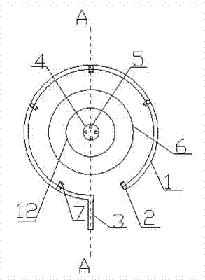
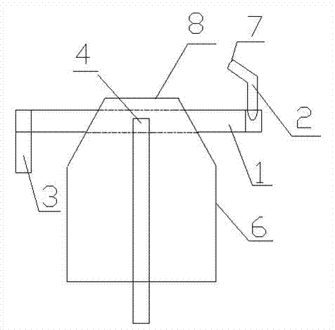
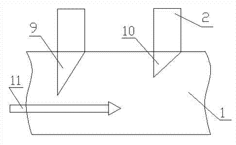
[0032] exist figure 1 In the embodiment shown in —4: the middle of the combustion-supporting air duct in the burner 6 gradually becomes smaller to the air outlet 12, and a plurality of swirl plates 13 are installed on the inner side of the smaller area, and the gradually smaller and band swirl plates 13 The combustion-supporting air duct of the burner 6 can make the combustion-supporting air entering from the air duct of the burner 6 have an inclination angle and swirl into the injected fuel flow at an angle of 10 degrees to 45 degrees to support combustion; the oxygen-enriched preheating pipe 1 in the furnace is surrounded by Around the burner 6 in the combustion furnace, it is attached or half-buried in the insulation layer around the burner 6, and the oxygen-enriched preheating pipe 1 in the furnace is welded with two or several oxygen-enriched nozzles distributed symmetrically with the burner 6 The pipe 2 and the oxygen-enriched nozzle 7 are connected to the oxygen-enriche...


PUM


Abstract

The self-preheating oxygen-enriched burner of the temperature-gathering furnace with oxygen-enriched nozzles includes burners burning gaseous or / and liquid fuels, as well as tubular oxygen-enriched preheaters surrounding the burners in the furnace and connected to On the tubular oxygen-enriched preheater, the small-diffusion-angle oxygen-enriched nozzles are symmetrically distributed around the burner. The combustion-supporting air duct in the burner gradually becomes smaller from the middle to the air outlet, and multiple swirls are installed inside the smaller area. plate, characterized in that: the swirl plate can make the combustion-supporting air entering from the burner swirl into the injected fuel flow at an angle of 10 degrees to 45 degrees, and the fuel nozzle sprays a fuel flow with a small diffusion angle on the front face of the burner Oxygen-lean combustion, and then through the oxygen-enriched nozzle in the furnace, the oxygen-enriched gas jet is sent into the combustion flame with oxygen-enriched combustion to improve the efficiency of heat radiation.

Description

technical field [0001] The invention relates to a self-preheating oxygen-enriched burner for a temperature-gathering type combustion furnace with an oxygen-enriched nozzle, which is suitable for all kinds of industrial boilers, heating furnaces, kilns, furnaces, incinerators, etc. of fuel and gas, and belongs to the comprehensive energy-saving and emission-reduction technology field and the field of combustion science and technology. Background technique [0002] With the development of industrial and agricultural deep-processing industries, our living environment is getting worse and worse, so the pressure of low-carbon economy and low-carbon life is becoming greater and greater; various industrial boilers in modern industry, Heating furnaces, kilns, furnaces, incinerators, etc. are the largest emitters of carbon dioxide and other emissions, so reducing emissions in industrial production is the key to realizing a low-carbon economy and protecting the living environment of h...

Claims


Application Information

Patent Timeline
Patent Type & Authority Applications(China)
IPC IPC(8): F23C5/08F23L7/00
CPCY02E20/34
Inventor 魏伯卿
Owner 魏伯卿
Why Eureka
Try Eureka