Efficient combined three-phase separator

A technology of three-phase separation and three-phase separator, which is applied in the field of combined three-phase separation device, gas, solid and liquid three-phase separation device, which can solve the problems of difficult installation, affecting separation effect and low separation efficiency , to achieve improved separation effect, easy installation and use, and guaranteed separation effect

Inactive Publication Date: 2011-11-16
江苏中环环保科技有限公司
View PDF11 Cites 2 Cited by
  • Summary
  • Abstract
  • Description
  • Claims
  • Application Information

AI Technical Summary

Problems solved by technology

However, this kind of technology has not been able to solve the problem of the oversized and complicated installation of the integral three-phase separator. Even if some technologies have proposed the idea of ​​split and combined three-phase separators, they cannot be very good in practice. Good solution to the problem of low separation efficiency and incomplete separation effect
Judging from the existing technical literature, few people mention the structural improvement of the inverted V-shaped reflector. In the process of improving the three-phase separation device, ordinary technicians will replace the double-sided reflector with Triangular, quadrilateral or even polygonal shapes can easily form water flow gaps in the shell, resulting in the problem of direct current penetration of local upward water flow, which ultimately affects the separation effect. In addition, the cost of the transformation research process is relatively high, and the possibility of successful transformation is low. Therefore, the existing three-phase Although the separation device obviously has weaknesses such as low separation efficiency and difficult installation, few people are willing to improve it

Method used


Image

  • Efficient combined three-phase separator
  • Efficient combined three-phase separator
  • Efficient combined three-phase separator

Examples


Embodiment 1

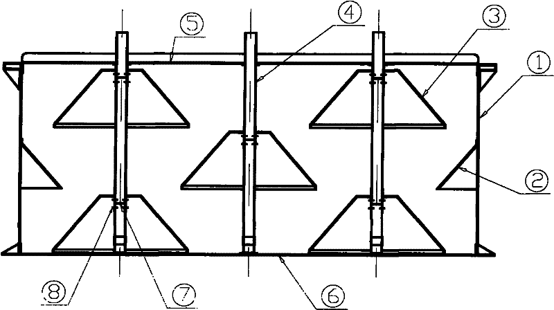
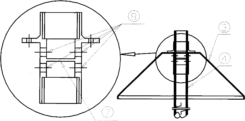
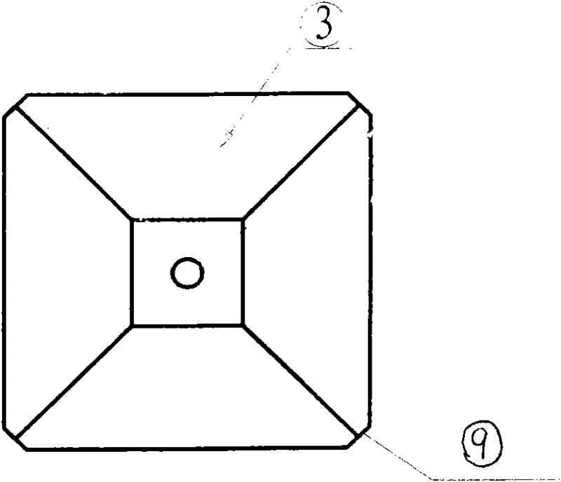
[0018] Embodiment 1: as figure 1 As shown, a high-efficiency combined three-phase separation device includes a three-phase separator shell 1 and a sloping plate 2 installed on the side of the shell. There are multiple inverted bucket-shaped reflectors arranged in the shell, which are large at the bottom and small at the top. Monomer 3, each reflector unit is arranged in a net shape in the shell, the reflector units on the same level in the horizontal direction are basically kept in a horizontal state, and the reflector units on the same level in the vertical direction are in a vertical state, and two different levels adjacent to each other The reflector units are slightly staggered. Among them, the mouth of the bucket-shaped reflector unit 3 faces downward, and the corners 9 of the mouth are chamfered at 45 degrees to form a square shape with missing corners; the top of the bucket-shaped reflector unit is an air chamber 10, and the passage between each air chamber The air col...

Embodiment 2

[0019] Embodiment 2: A high-efficiency combined three-phase separation device, including a three-phase separator housing 1 and a sloping plate 2 installed on the side of the housing, a plurality of reflecting plate monomers 3 are arranged in the housing, and two adjacent The reflectors are arranged staggeredly in the horizontal or vertical direction. The reflectors are in the shape of an inverted bucket with a large bottom and a small top. The rear is in the shape of a square with missing corners; the top of the bucket-shaped reflecting plate is an air chamber 10, and the air chambers are connected in series through the air collecting pipe 4. There is a separator 7 inside the air collecting pipe 4, and the air inlet and outlet holes 8 are respectively opened on the upper and lower parts of the air collecting pipe. in a horizontal or vertical stagger.


PUM


Abstract

The invention discloses an efficient combined three-phase separator, which comprises a three-phase separator shell and a sloping plate installed at the side of the shell, wherein a plurality of reflection plate single bodies are alternately arranged in horizontal and vertical directions inside the three-phase separator shell, and the reflection plate single bodies are in a bucket shape with large bottom and small top. As a further improvement of the efficient combined three-phase separator, the bucket-shaped reflection plate single body is provided with a mouth part in an unfilled-corner square shape with a downward opening and air chambers at the top, the air chambers are connected in series by an air collecting pipe, a partition is arranged inside the air collecting pipe, and air inflow and outflow holes are separately formed on the upper and lower parts of the partition. The efficient combined three-phase separator provided by the invention has the advantage of high separation efficiency, good separation effect and easiness in installation.

Description

technical field [0001] The invention relates to a separation device for separating solid, gas and liquid three phases, in particular to a combined three-phase separation device. It belongs to the field of sewage treatment. Background technique [0002] The three-phase separation device is an important structure and equipment of anaerobic reactors such as UASB, EGSB, and IC. It plays a very important role in the normal operation of the sludge bed and obtaining good effluent water quality. Three-phase separation is to separate the anaerobic activated sludge (solid phase), sewage (liquid phase) and biogas (gas phase) in the tank. The anaerobic activated sludge is collected and retained in the tank to continue processing sewage, and the biogas is collected into the biogas tank as Fuel recovery, sewage is treated and separated and then flows out to the next treatment unit. [0003] The current common three-phase separation device is generally an integral type, mainly composed o...

Claims


Application Information

Patent Timeline
Patent Type & Authority Applications(China)
IPC IPC(8): C02F3/28
Inventor 倪志刚花成巍
Owner 江苏中环环保科技有限公司
Why Eureka
Try Eureka