Organic compound steam generator and apparatus for producing organic thin film

A steam generating device and organic compound technology, which can be used in lighting devices, vacuum evaporation coating, devices for coating liquid on surfaces, etc., and can solve problems such as backflow of organic material vapor

Active Publication Date: 2011-11-09
ULVAC INC
View PDF9 Cites 2 Cited by
  • Summary
  • Abstract
  • Description
  • Claims
  • Application Information

AI Technical Summary

Problems solved by technology

[0008] In the conventional steam generator 130, there is a problem that the organic material steam generated in the generating tank 133 flows back into the tubular insertion part 128.

Method used


Image

  • Organic compound steam generator and apparatus for producing organic thin film
  • Organic compound steam generator and apparatus for producing organic thin film
  • Organic compound steam generator and apparatus for producing organic thin film

Examples


Embodiment Construction

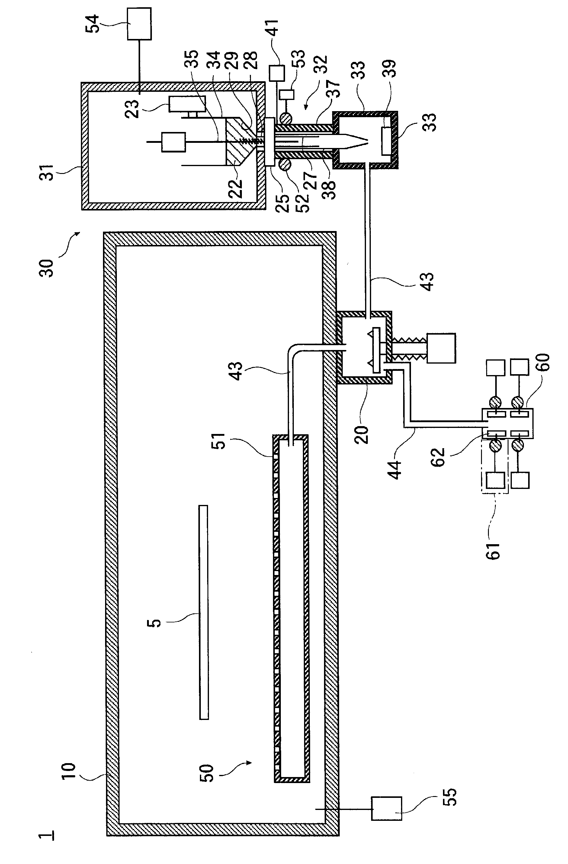
[0057] figure 1 Reference numeral 1 is an organic thin film production device (vapor deposition device) according to an example of the present invention.

[0058] This organic thin film manufacturing apparatus 1 has a film forming tank 10 , a steam generating device 30 , and a steam releasing device 50 .

[0059] The steam releasing device 50 is arranged inside the film forming tank 10 . The steam generator 30 is connected to the steam release device 50 via the connection valve 20 , and when the connection valve 20 is turned on, the steam of the organic compound generated in the steam generator 30 is supplied to the steam release device 50 . The organic compound vapor supplied to the vapor releasing device 50 is released from a plurality of releasing ports 51 of the vapor releasing device 50 into the film forming tank 10 in a vacuum environment.

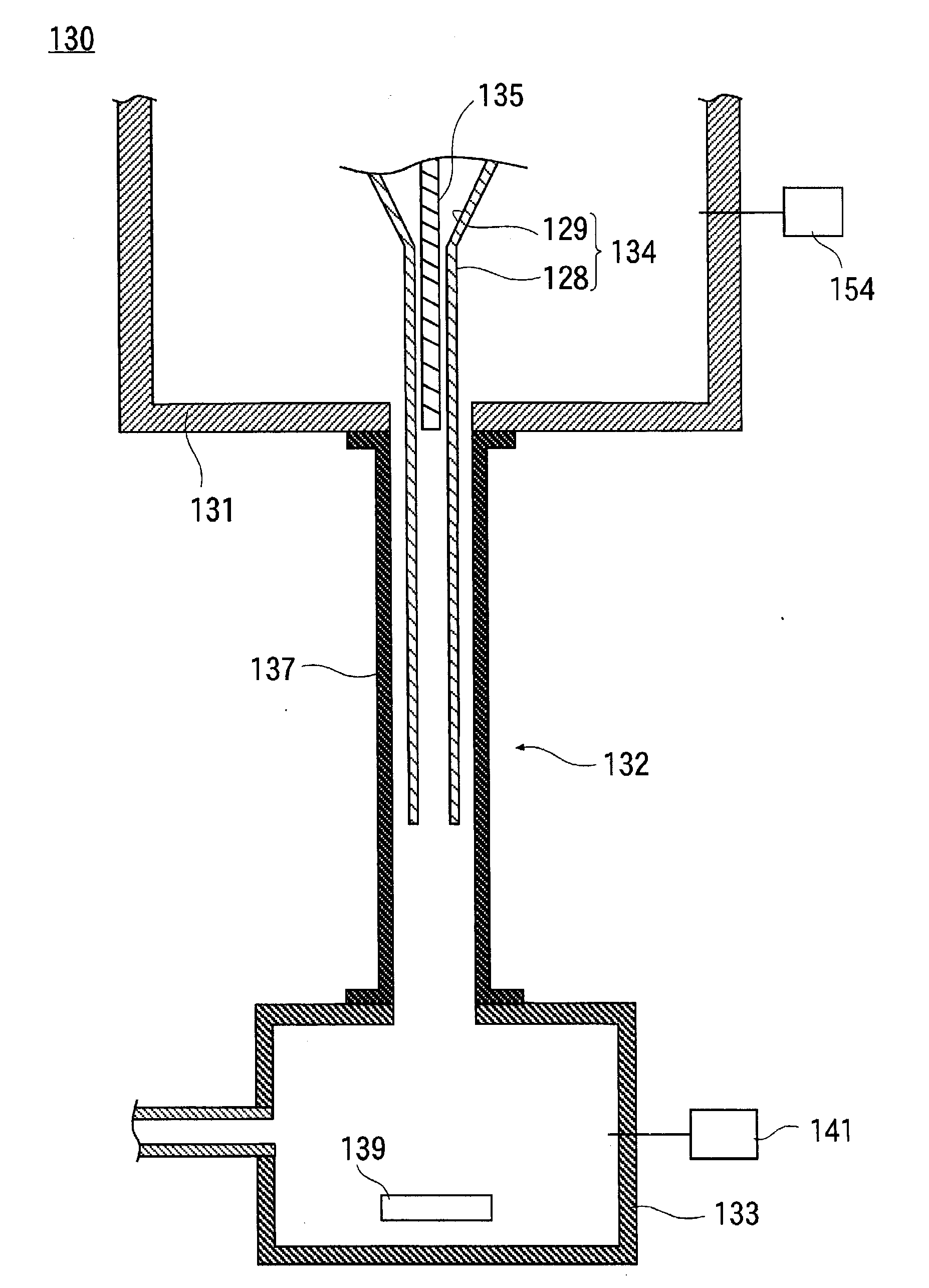
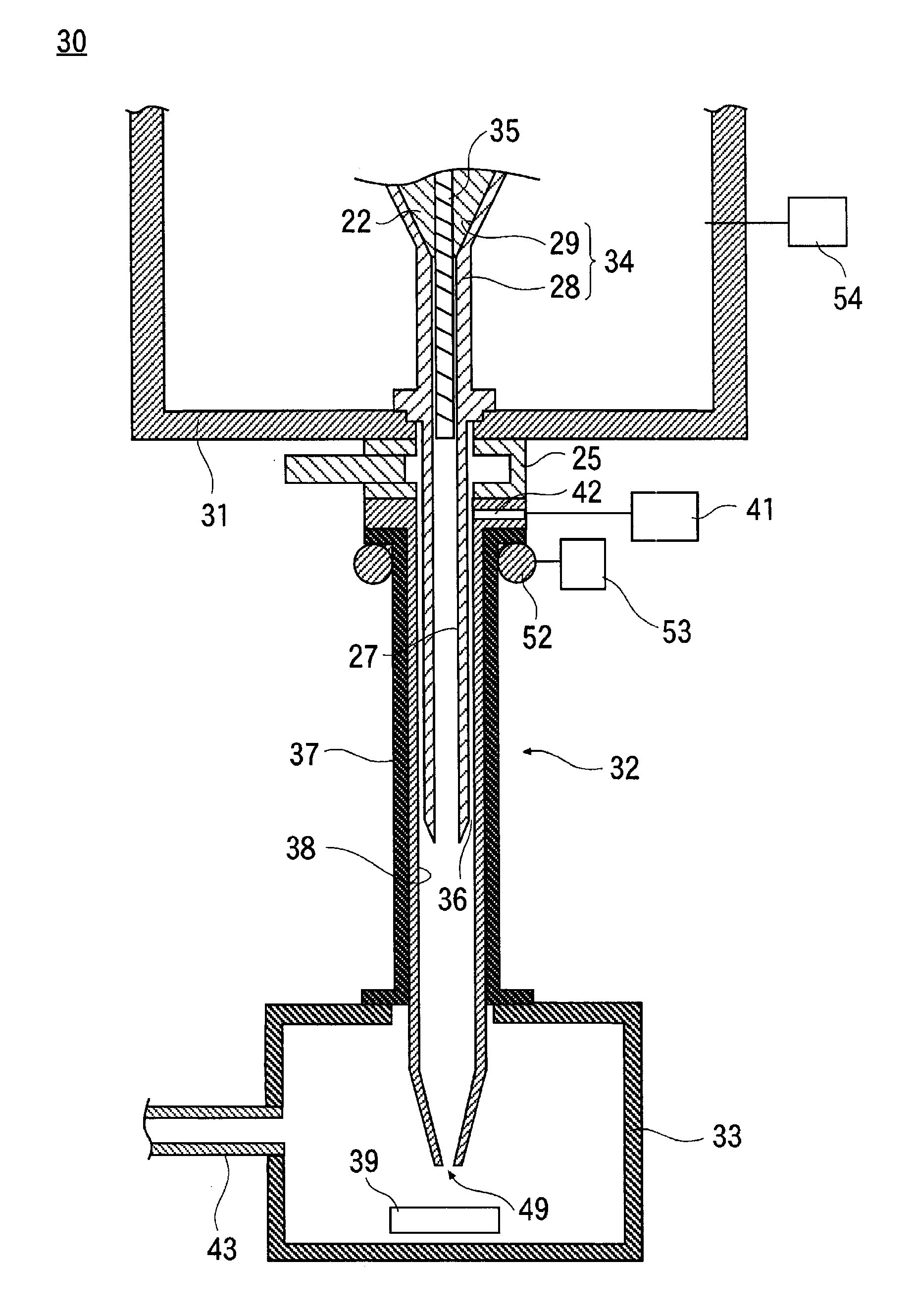
[0060] figure 2The shown steam generator 30 is an example of the present invention, and has a storage tank 31 , a transport de...


PUM


Abstract

Provided is technology with which organic compound steam generated inside a generating tank does not flow back into an inner connecting pipe through which organic compound is fed to the generating tank. An apparatus (1) for producing an organic thin film comprises a reservoir (31) in which organic materials are disposed, a generating tank (33) for heating the organic materials and generating steam from the organic materials, and a transport apparatus (32) for feeding the organic materials inside the reservoir (31) to the generating tank (33). The transport apparatus (32) has an outer connecting pipe (37), which forms an airtight connection between the atmosphere inside the reservoir (31) and the atmosphere inside the generating tank (33); a quartz inner connecting pipe (38), which is disposed inside the outer connecting pipe (37) and moves organic materials from the inside of the reservoir (31) to the inside of the generating tank (33); and a gas introduction port (42) for the introduction of gas into the inner connecting pipe (38).

Description

technical field [0001] The present invention relates to an evaporation source for manufacturing organic EL and an organic EL manufacturing device. Background technique [0002] image 3 The shown conventional steam generator 130 has a storage tank 131 , a transport device 132 , and a generator tank 133 . [0003] Inside the storage tank 131, a funnel-shaped funnel container 134 is arranged vertically. The funnel container 134 has an inverted conical funnel slope 129 and a tubular insertion portion 128 as a tube connected to a hole at the center of the funnel shape. The tubular insertion portion 128 extends vertically downward, and the metering rod 135 is inserted vertically from a position above the upper end of the tubular insertion portion 128 to the inside of the tubular insertion portion 128 . [0004] A generation tank 133 is disposed below the storage tank 131 , and the conveying device 132 is disposed between the storage tank 131 and the generation tank 133 . [00...

Claims


Application Information

Patent Timeline
Patent Type & Authority Applications(China)
IPC IPC(8): C23C14/24C23C16/448H01L51/50H05B33/10
CPCB05D1/60C23C14/12H01L51/56C23C14/243C23C14/228C23C14/246H01L51/001H10K71/164C23C14/24
Inventor 根岸敏夫平岩秀行
Owner ULVAC INC
Why Eureka
Try Eureka