
Method and device for preventing boiler waste heat recovery hot water from causing cavitation on boiler feed pump

A boiler feed water pump and hot water recovery technology, which is applied to supplementary feed water, preheating, pump components, etc., can solve the problems of increased production and installation costs, and achieve the effects of less installation cost, less reserve, and less surface heat dissipation area.

Inactive Publication Date: 2011-10-26
CHEMCHINA ZHUZHOU RUBBER RES & DESIGN INST
View PDF5 Cites 1 Cited by
  • Summary
  • Abstract
  • Description
  • Claims
  • Application Information

AI Technical Summary

Problems solved by technology

It is bound to cause a great increase in production and installation costs

Method used

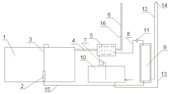

Image

  • Method and device for preventing boiler waste heat recovery hot water from causing cavitation on boiler feed pump
  • Method and device for preventing boiler waste heat recovery hot water from causing cavitation on boiler feed pump
  • Method and device for preventing boiler waste heat recovery hot water from causing cavitation on boiler feed pump

Examples


Embodiment 1

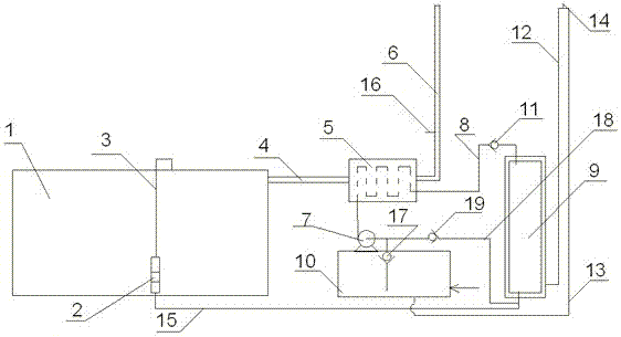
[0016] According to the above-mentioned method, the device for preventing boiler waste heat from recovering hot water from causing cavitation of the boiler feed pump is shown in the attached figure 2As shown, the boiler body 1 is included, the boiler body 1 is provided with a flue discharge pipe 4, and a heat exchanger 5 is installed in the flue discharge pipe section 4, the heat exchanger 5 is a water-cooled heat exchanger, and the heat exchanger 5 The water inlet of the water tank 10 communicates with the water supply tank 10, and the heat exchanger 5 replenishes water through the water supply tank 10; the water outlet of the heat exchanger 5 communicates with an external hot water tank 9 through a pipeline 8, and the heat exchanger is connected to the heat exchanger through a waste heat circulating water pump 7. The hot water in 5 is extracted and poured into the hot water tank 9, the bottom of the hot water tank 9 is provided with a hot water outlet, and the hot water outl...

Embodiment 2

[0019] The basic structure of this embodiment is the same as that of Embodiment 1, but the layout of pipelines is slightly different. In this embodiment, a circulation branch pipe 18 is connected to the water supply line 15 connecting the hot water tank to the boiler feed water pump. The water supply inlet pipelines are connected, and at the same time, the suction pipe section of the water supply inlet pipeline of the waste heat circulating water pump 7 is provided with an electronically controlled one-way valve 17, and the electronically controlled one-way valve 17 is closed when the water in the hot water tank 9 is sufficient. A one-way circulation loop is formed between the heat exchanger 5, the waste heat circulating water pump 7 and the hot water tank 9, so that the water temperature of the hot water tank can be further increased; at the same time, in order to prevent water from directly flowing into the boiler feed water pump 2 from the circulation branch pipe 18, in the ...


PUM


Abstract

The invention relates to a method and device for preventing boiler waste heat recovery hot water from causing cavitation on a boiler feed pump. In the invention, a heat exchanger is arranged on the outlet pipe section of a flue, the smoke discharged by a boiler exchanges heat with the water in the heat exchanger and then is discharged; the heat exchanger carries out the heat exchange through inputting cold water, the cold water in the hot exchanger is provided by the water-replenishing tank of the boiler; the cold water in the water-replenishing tank of the boiler is sent to the heat exchanger through a waste heat water circulating pump, and then the cold water is subjected to heat exchange so as to become hot water, and the hot water enters into a heat-preservation hot water tank, the hot water is sent into the boiler feed pump from the lower part of the hot water tank through a pipeline, the boiler feed pump serving as a water source supplies water for the boiler; and a pressure-keeping device is arranged on the side of the hot water tank, the pressure-keeping device is communicated with the hot water tank through a pipeline, and the pressure-keeping device can ensure that the boiler feed pump has water pressure for preventing water pump hot water from causing cavitation when the boiler feed pump is started.

Description

technical field [0001] The present invention relates to a boiler water supply method and device, in particular to a method and device for preventing cavitation of the boiler feed water pump caused by hot water in providing hot water for the boiler by using waste heat recovery, mainly used in gas-fired boilers, but also It can be applied to other boiler waste heat recovery devices or hot water supply devices. Background technique [0002] When designing and manufacturing industrial oil-fired, gas-fired and coal-fired boilers, in order to prevent corrosion and ash blocking of the heating surface at the boiler tail, the standard state exhaust gas temperature is generally not lower than 180°C, and the maximum can reach 250°C. High-temperature flue gas emissions not only cause a lot of waste of heat energy , but also pollute the environment. Recovering the heat in the flue gas to heat the boiler to make up water can greatly improve the efficiency of energy utilization. Thereby ...

Claims


Application Information

Patent Timeline
Patent Type & Authority Applications(China)
IPC IPC(8): F22D11/02F04B11/00
Inventor 谭丁铁王资院
Owner CHEMCHINA ZHUZHOU RUBBER RES & DESIGN INST
Learn More