Rock drilling machine and axial bearing module

A technology for axial bearings and rock drilling machines, which is applied in the field of rock drilling machines, can solve the problems of difficult assembly and replacement of axial bearings, complicated maintenance, strain, etc., and achieves the effects of facilitating disassembly and installation, light structure, and small size

Inactive Publication Date: 2011-10-19
SANDVIK MINING & CONSTR OY
View PDF3 Cites 3 Cited by
  • Summary
  • Abstract
  • Description
  • Claims
  • Application Information

AI Technical Summary

Problems solved by technology

A disadvantage of known axial bearings is that their maintenance is complicated and slow
In addition, the assembly of the axial bearing and possible later replacement of the components is difficult
Yet another detected problem of the axial bearing solution is that the support force caused by the operation of the axial bearing causes unnecessary strain on the structure of the rock drilling machine

Method used


Image

  • Rock drilling machine and axial bearing module
  • Rock drilling machine and axial bearing module
  • Rock drilling machine and axial bearing module

Examples


Embodiment Construction

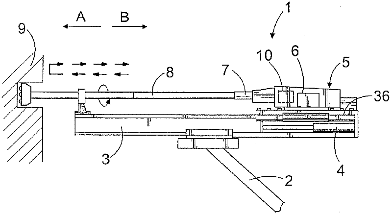
[0041] figure 1 A rock drilling unit 1 is shown which may be arranged on a drill boom 2 or the like of a rock drilling rig. The rock drilling unit 1 may comprise a feed beam 3 on which a rock drilling machine 5 is arranged and moved by means of a feed device 4 . The rock drilling machine 5 can be fastened to the carriage 36 and can be moved in the striking direction A and in the returning direction B. As shown in FIG. Furthermore, the rock drilling machine 5 comprises a percussion device 6 for generating a percussion pulse on the drill shank 7 and passing the percussion pulse further through the tool 8 to the rock 9 . Tool 8 may include one or more drill rods and drill bits. Alternatively, the tool 8 may be a one-piece drill rod, in which case a machine component like the drill shank 7 may be considered to be fixedly connected to its end on the rock drilling machine side. Therefore, in this patent application, a drill shank may also refer to the rear end of a one-piece dril...


PUM


Abstract

The invention relates to a rock drilling machine and an axial bearing module. The rock drilling machine (5) is equipped with an axial bearing (18) having at least one axial piston (19, 20) for axially positioning a drill shank (7) and for damping stress pulses returning from the rock. The axial bearing comprises a module (21) that is detachable in one piece from one installation direction. The axial bearing module comprises the required pressure medium channels (27), seals (37, 37a, 37b, 37c), bearing surfaces (18), and a module frame (22, 25, 38a, 38b) having at least bearing housing in connection therewith.

Description

technical field [0001] The invention relates to a rock drilling machine comprising a body, a percussion element arranged inside the body and also a drill shank to which a tool can be connected for breaking rock. The percussion device includes a percussion element that generates a stress pulse to the tool through the shank. Furthermore, the rock drilling machine comprises an axial bearing with one or more pressure medium operated axial pistons, with which the shank can be pushed in the axial direction relative to the body by a predetermined travel length in the striking direction. The impact surface of the shank can then be set at the desired axial point for receiving the stress pulse. The axial piston is operated by means of a pressure medium, wherein the axial piston comprises a working pressure surface positioned in a working pressure space belonging to the axial bearing, the pressure of which can be fed from the feed channel into the working pressure space. Force can then...

Claims


Application Information

Patent Timeline
IPC IPC(8): B25D17/06B25D17/24B25D9/14E21B1/38E21B6/00
CPCB25D9/14B25D17/06B25D17/24B25D2250/331E21B6/00E21B7/025B25D17/26B25D9/125
Inventor 蒂莫·穆托宁拉斯·坎德林佩卡·绍科
Owner SANDVIK MINING & CONSTR OY
Why Eureka
Try Eureka