
Mobile self-cleaning dry dust-collecting and ventilating equipment used in tunnel construction

A technology for tunnel construction and ventilation equipment, which is applied in mine/tunnel ventilation, mining equipment, dust prevention, etc. It can solve problems such as secondary pollution, and achieve the effects of saving operating costs, saving equipment investment, and optimizing ventilation systems

Inactive Publication Date: 2011-10-12
金承官
View PDF5 Cites 22 Cited by
  • Summary
  • Abstract
  • Description
  • Claims
  • Application Information

AI Technical Summary

Problems solved by technology

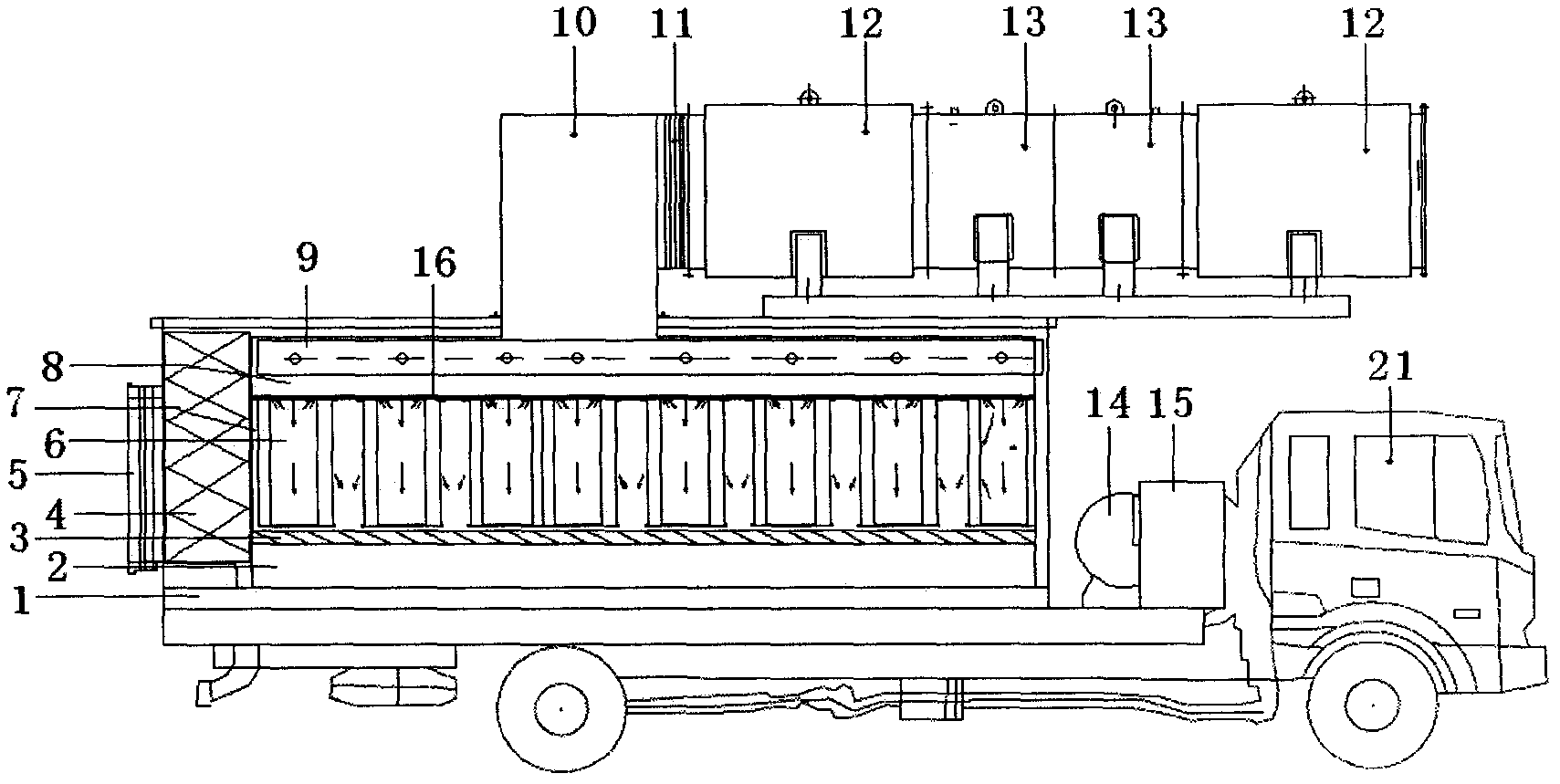
[0003] The purpose of the present invention is to solve the secondary pollution problem caused by the untreated dust air being directly discharged by the exhaust fan in the engineering for the purification and discharge of the dust air produced on the construction work surface of the railway and highway tunnel, and to have the tunnel construction ventilation function as Integrated, dust collection and purification and air supply / exhaust operations are carried out by the truck as the equipment carrier

Method used


Image

  • Mobile self-cleaning dry dust-collecting and ventilating equipment used in tunnel construction
  • Mobile self-cleaning dry dust-collecting and ventilating equipment used in tunnel construction
  • Mobile self-cleaning dry dust-collecting and ventilating equipment used in tunnel construction

Examples


Embodiment Construction

[0019] The equipment of the present invention usually takes a truck as a carrier, and is arranged at the excavation surface. When the dust generated by the tunnel construction and the flue gas produced by the internal combustion engine are sucked into the dust removal box 1 through the dust suction port 5 under the negative pressure generated by the counter-rotating jet fan 13, the large particle dust and The water vapor contained in the dust is separated. The small particle fiber dust (below 5 μm) filtered by the defoaming / demisting device enters the antistatic filter cartridge 6 filter system in the filter box 7 . At this time, negative pressure is also generated in the antistatic filter cartridge 6, and the smoke and dust air outside the filter cartridge enters the antistatic filter cartridge 6 under the action of pressure difference, and the dust is blocked on the outer surface of the filter cartridge, and the blocked dust falls into the collector under the action of gravi...


PUM


Abstract

The invention provides mobile self-cleaning dry dust-collecting and ventilating equipment used in tunnel construction, and belongs to the field of energy-saving and environmentally-friendly electromechanical equipment. In the invention, dust generated in tunnel construction and flue gas generated by an internal combustion engine enter into an equipment body via a dust sucking port under the action of negative pressure generated by a contra-rotating jet fan; firstly large dust particles are separated from water vapor contained in the dust by utilizing a demister; the filtered small dust particles enter a filter system, smoke outside a filter cartridge enters the filter cartridge under the action of differential pressure, meanwhile the dust is obstructed on the external surface of the filter cartridge, and the obstructed dust falls into a dust collecting chamber under the action of gravity; and after the filter cartridge operates for a period of time, part of the filtered dust is still deposited on the surface of the filter cartridge, thus a reverse soot-blowing program is carried out at the moment, firstly a diaphragm valve bank in a certain filter unit is closed, the negative pressure in the filter cartridge is cut off, then a corresponding solenoid valve group is opened, and finally positive air pressure in a pulse soot-blowing tube is released so as to reversely blow off soot towards the interior of the filter cartridge from inside to outside. By utilizing the mobile self-cleaning dry dust-collecting and ventilating equipment, the number of the ventilating equipment in tunnel construction is reduced, the input cost and operating electricity fee of the fan are saved, and the operating environment is improved.

Description

technical field [0001] The invention belongs to the field of energy-saving and environment-friendly electromechanical equipment, and is a mobile self-cleaning dry-type dust-collecting and ventilating device with a truck as a carrier for the dust and smoke generated in the construction process of railways and traffic tunnels. Background technique [0002] At present, most of the super-long tunnel construction ventilation systems use water-based wet dust removal technology, such as spray watering, water curtain dust reduction, pulse jet bag type dust removal equipment, electrostatic dust removal, etc. Wet dust removal is generally adopted because of its small size, simple operation and low equipment cost. However, the processing air volume of wet dust removal is small, the atomization is not good, and the dust removal efficiency is not high. Moreover, the water mist affects the line of sight, and the discharged sewage affects the construction and slag removal transportation. ...

Claims


Application Information

Patent Timeline
IPC IPC(8): E21F5/20E21F1/00
Inventor 金承官
Owner 金承官
Learn More