
Detachable optical glass successive melting furnace

An optical glass and melting furnace technology, applied in glass production, furnaces, boilers, etc., can solve the problems of glass liquid leakage, damage, aging of platinum utensils, etc.

Active Publication Date: 2011-10-05
HUBEI NEW HUAGUANG NEW INFORMATION MATERIALS CO LTD
View PDF3 Cites 12 Cited by
  • Summary
  • Abstract
  • Description
  • Claims
  • Application Information

AI Technical Summary

Problems solved by technology

[0003] Since the optical glass is connected with the various parts of the furnace through pipes, the furnace will be deformed due to the expansion effect during the heating process, or the phenomenon of thermal expansion and contraction due to temperature fluctuations will easily cause the aging of platinum vessels, cause damage, and cause glass Fluid leaking, repair required
Because it is necessary to wait for the temperature of the furnace to drop to normal temperature before maintenance can be carried out, and after maintenance, the temperature needs to be raised to the process temperature, resulting in a long shutdown time of the furnace and low production efficiency of the furnace

Method used


Image

  • Detachable optical glass successive melting furnace
  • Detachable optical glass successive melting furnace
  • Detachable optical glass successive melting furnace

Examples


Embodiment Construction

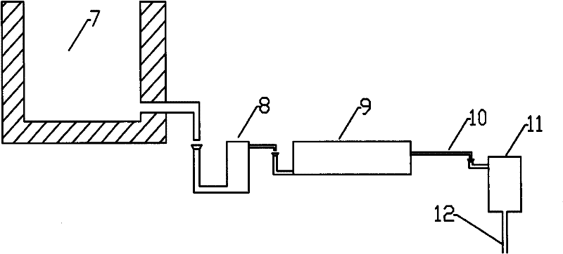
[0015] The device of the present invention is as figure 2 As shown, it includes a melting furnace 7 , a heating furnace 8 , a clarifying furnace 9 , a cooling portion 10 , a working furnace 11 , and a leakage pipe 12 . The furnace 7 of the melting part, the furnace 8 of the heating part, and the furnace 9 of the clarification part are connected through pipelines, and the furnace 9 of the clarification part, the pipeline 10 of the cooling part, and the furnace 11 of the working part are connected in sequence, and the pipe ports are non-contact connected to form a flow channel of molten glass.

[0016] figure 2 The melting furnace 7 in the middle melting part can be a container made of ceramic crucible, quartz crucible, refractory material, platinum crucible and the like. The rest of the containers can be platinum crucibles, quartz crucibles, ceramic crucibles or other high temperature resistant metal containers.

[0017] The detachable optical glass continuous melting furna...


PUM


Abstract

The invention, which relates to a detachable optical glass successive melting furnace and belongs to the technical field of optical glass melting devices, mainly solves the problem that the present melting furnaces highly lead to the aging of platinum vessels which further results in the damage of the platinum vessels, the blowing out of furnaces and long maintenance time. The detachable optical glass successive melting furnace is characterized by comprising successively connected parts of a fusing-section smelting furnace, a heating-section smelting furnace, a clarification-section smelting furnace, a cooling-section pipeline and a working-section smelting furnace, wherein the fusing-section smelting furnace, the heating-section smelting furnace and the clarification-section smelting furnace are connected by connecting pipes; the fusing-section smelting furnace, the heating-section smelting furnace, the clarification-section smelting furnace and the working-section smelting furnace are all equipped with an independent heating device; and the connection pipelines connecting the fusing-section smelting furnace, the heating-section smelting furnace and the clarification-section smelting furnace and the cooling-section pipeline are all provided with a flow control device. The detachable optical glass successive melting furnace provided by the invention has the summing effect of minimizing the container expansion, reduces the crucible damage, is convenient for maintenance, raises the smelting furnace production efficiency, and is mainly used in optical glass successive melting furnaces which can be split and assembled.

Description

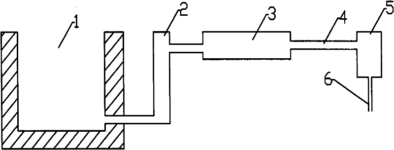
technical field [0001] The invention belongs to the technical field of optical glass melting devices. It specifically relates to a continuous melting furnace for optical glass which is suitable for continuous melting of optical glass and can be disassembled for assembly. Background technique [0002] A common optical glass continuous melting furnace is composed of a melting part 1, a heating part 2, a clarifying part 3, a cooling part 4, and a working part 5, and the working part 5 is provided with a leakage pipe 6. All parts are connected through corresponding pipes to complete the flow of glass from the melting part to the working part in sequence. During the flow process, glass defects such as bubbles and streaks in the molten glass are gradually removed to obtain high-quality and high-performance optical products. [0003] Since the optical glass is connected to the various parts of the furnace through pipes, the furnace will be deformed due to the expansion effect duri...

Claims


Application Information

Patent Timeline
IPC IPC(8): C03B5/06C03B5/08
CPCY02P40/57
Inventor 姜敬陆张卫
Owner HUBEI NEW HUAGUANG NEW INFORMATION MATERIALS CO LTD
Learn More