Imaging device and imaging system
A technology of a camera device and a camera unit, which is applied to parts of a TV system, image enhancement, image communication, etc., can solve problems such as uneven brightness, uneven color, and deviation, and achieve the effect of removing uneven color.
- Summary
- Abstract
- Description
- Claims
- Application Information
AI Technical Summary
Problems solved by technology
Method used
Image
Examples
Embodiment approach 1
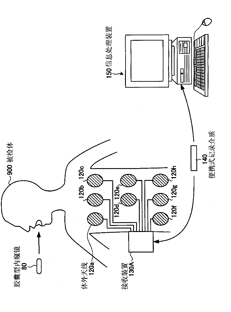
[0039] figure 1 It is a schematic diagram showing the configuration of the capsule endoscope system according to Embodiment 1 of the present invention. Such as figure 1 As shown, the endoscope system according to Embodiment 1 includes: a capsule endoscope 2 that captures in-vivo images of the subject 1; and a receiving device 3 that receives images wirelessly transmitted by the capsule endoscope 2. signal; an image display device 4 that displays an in-vivo image captured by the capsule endoscope 2 ; and a portable recording medium 5 that is used for data exchange between the receiving device 3 and the image display device 4 .
[0040] The capsule endoscope 2 has an imaging function and a wireless communication function inside the capsule casing. After the capsule endoscope 2 is introduced into the organ of the subject 1 by oral ingestion or the like, the capsule endoscope 2 moves inside the organ of the subject 1 by peristaltic motion or the like, and moves at a predetermi...
Embodiment approach 2
[0061] Next, Embodiment 2 of the present invention will be described. When the light irradiated by the light emitting element is specularly reflected like a mirror, the luminance is saturated in the specularly reflected area, and becomes a high luminance area. Here, when light emitting elements having different wavelength ranges of the blue wavelength range and the green wavelength range are arranged at different positions, as in Figure 11 As shown, according to the area of the acquired image, there is a high brightness area E20 and a false color area E21, the blue signal level and the green signal level of the high brightness area E20 are saturated, and the false color area E21 is distributed in the high brightness area around , only one of the blue signal level or the green signal level is saturated. exist Figure 11 , only the blue signal level becomes saturated in the false color region E21.
[0062] Therefore, in Embodiment 2, the color unevenness correcting unit 55...
Embodiment approach 3
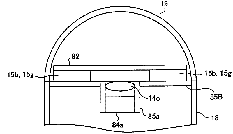
[0066] Next, Embodiment 3 of the present invention will be described. In Embodiment 3, the light distribution characteristics, that is, the directional characteristics of light emission, of the light-emitting elements arranged in different positions in the blue wavelength range and the green wavelength range are changed so that color unevenness does not occur as much as possible.
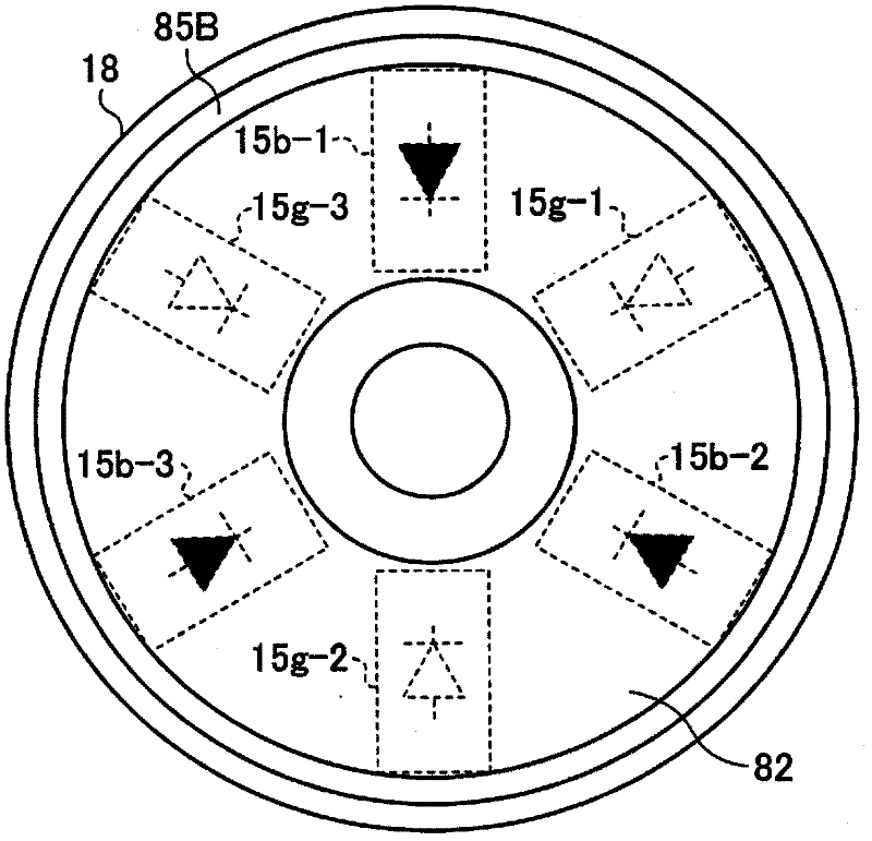
[0067] Such as image 3 As shown, when each LED 10, 11 is arranged in a circular shape, as Figure 9 The image shown is an image in which the color is uneven in a plurality of areas, and the color unevenness occurs in the outer areas of the image. This is because each LED emits light in a non-directional manner, and the level of light emitted radially outward is small. Therefore, by Figure 12 By arranging LEDs having emission directivity 80 in which the level of light emitted radially increases as shown, the luminance distribution of the acquired image becomes flat, and the magnitude of color un...
PUM
 Abstract
Description
Claims
Application Information
 - Generate Ideas
- Intellectual Property
- Life Sciences
- Materials
- Tech Scout
- Unparalleled Data Quality
- Higher Quality Content
- 60% Fewer Hallucinations
Browse by: Latest US Patents, China's latest patents, Technical Efficacy Thesaurus, Application Domain, Technology Topic, Popular Technical Reports.
© 2025 PatSnap. All rights reserved.Legal|Privacy policy|Modern Slavery Act Transparency Statement|Sitemap|About US| Contact US: help@patsnap.com


