Method for preparing microstructural target by using laser to improve laser propulsion impulse coupling coefficient
An impulse coupling and microstructure technology, applied in laser welding equipment, welding equipment, manufacturing tools, etc., can solve problems such as unseen processing design, and achieve the effect of reducing heat conduction effect and eliminating heat conduction effect.
- Summary
- Abstract
- Description
- Claims
- Application Information
AI Technical Summary
Problems solved by technology
Method used
Image
Examples
Embodiment 1
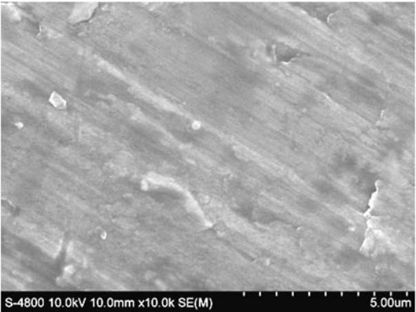
[0031] In the first step, the 10×10×2 cubic millimeter block aluminum target sample is ground and mechanically polished with 400-800 water sandpaper step by step, and the scanning electron micrograph of the sample surface is as follows: figure 1 shown. Ultrasonic cleaning with deionized water, then place it in a clean open container for use;
[0032] In the second step, a high-sensitivity torsion balance device was established to accurately measure the momentum generated by the above-mentioned ordinary metal aluminum target sample during the ablation laser propulsion process, and to study the enhancement degree of the impulse coupling. Experimental device such as Figure 5 (a) shown. In order to prevent the influence of air flow on the measurement of the torsion balance, the entire torsion balance device is placed in an airtight plexiglass cover. The ultra-short laser pulses used to ablate the target and the He-Ne laser signals used to detect the rotation of the torsion bal...
Embodiment 2
[0036] The first step is the same as in Example 1.
[0037] In the second step, in the air environment, the incident femtosecond laser pulse is vertically focused on the solid metal aluminum target sample processed in the first step using a microscope objective lens or an optical lens, and the sample surface is adjusted to In the range of 10-250 microns away from the focal plane;
[0038] The third step is to set the experimental parameters for femtosecond laser preparation: pulse repetition frequency 1 kHz, pulse width 50 femtoseconds, pulse center wavelength 800 nanometers, and the distance between adjacent laser processing scribe lines can be 20-100 microns The scanning speed of sample movement can be selected within the range of 0.05-1 mm / s, and the polarization direction of femtosecond laser and the scanning direction of sample movement can be at any angle.
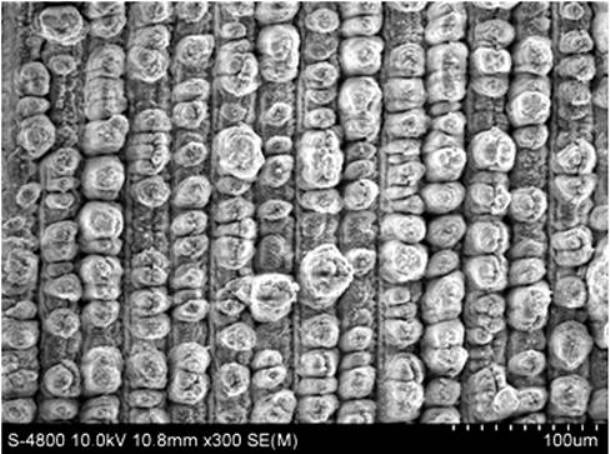
[0039] The fourth step is to adjust the average power of the incident laser pulse to 40 milliwatts. After the met...
Embodiment 3
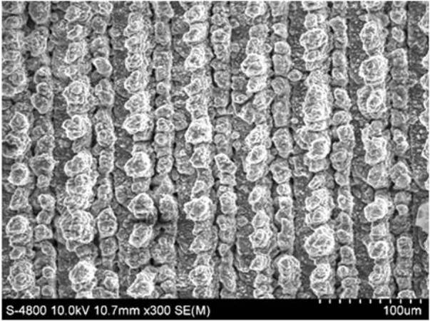
[0044] Except that the average power of the incident laser pulse was adjusted to 140 milliwatts during the preparation of the microstructured solid target by the femtosecond laser, other technical steps and experimental conditions were the same as in Example 2. In this case, it was observed experimentally that the surface of the metal aluminum target sample irradiated by the femtosecond laser also formed a stripe-like microstructure formed by a plurality of protrusions, and the scanning electron micrograph is shown in image 3 shown. and figure 2 In comparison, we know that when the incident laser power becomes larger, the size of the convex structure formed on the surface of the metal aluminum target sample gradually becomes smaller. The relationship between the impulse coupling coefficient of the surface microstructure metal aluminum target sample and the laser flow rate is as follows: Figure 6 of shown in the curve. We found that under this condition, the microstruct...
PUM
| Property | Measurement | Unit |
|---|---|---|
| power | aaaaa | aaaaa |
| power | aaaaa | aaaaa |
Abstract
Description
Claims
Application Information
 - R&D
- Intellectual Property
- Life Sciences
- Materials
- Tech Scout
- Unparalleled Data Quality
- Higher Quality Content
- 60% Fewer Hallucinations
Browse by: Latest US Patents, China's latest patents, Technical Efficacy Thesaurus, Application Domain, Technology Topic, Popular Technical Reports.
© 2025 PatSnap. All rights reserved.Legal|Privacy policy|Modern Slavery Act Transparency Statement|Sitemap|About US| Contact US: help@patsnap.com


