Multi-stage themolysis coupled denitration method using front flow field uniformizing device and device thereof

A uniform and flow field technology, applied in the field of multi-stage pyrolysis coupling denitrification method and its devices, can solve the problems of difficult control of ammonia escape, large initial investment, high operating cost, etc., to save reducing agent injection system, improve utilization rate, The effect of simple equipment

Active Publication Date: 2014-07-02
ZHEJIANG UNIV
View PDF9 Cites 0 Cited by
  • Summary
  • Abstract
  • Description
  • Claims
  • Application Information

AI Technical Summary

Problems solved by technology

The SNCR method has a simple system, simple construction, low initial investment, and low operating cost, but its biggest defect is the low denitrification rate, which is only 30-50% in power plant coal-fired boilers, and the SNCR method is difficult for ammonia to escape. control, affecting the stability and safety of boiler operation
The SCR method has high denitrification efficiency. Because the mixer, ammonia injection grid and flue gas rectifier can well realize the uniform mixing of reducing agent and NO in flue gas, the denitrification rate can reach more than 95%, but its disadvantage is that it occupies an area Large, complex system, large initial investment, high operating cost
Mixed SNCR-SCR denitrification technology is also used on coal-fired boilers, but it is difficult to achieve uniform mixing of reducing agent and NO in flue gas, so the denitrification rate of SNCR-SCR method is not satisfactory

Method used


Image

  • Multi-stage themolysis coupled denitration method using front flow field uniformizing device and device thereof
  • Multi-stage themolysis coupled denitration method using front flow field uniformizing device and device thereof
  • Multi-stage themolysis coupled denitration method using front flow field uniformizing device and device thereof

Examples


Embodiment Construction

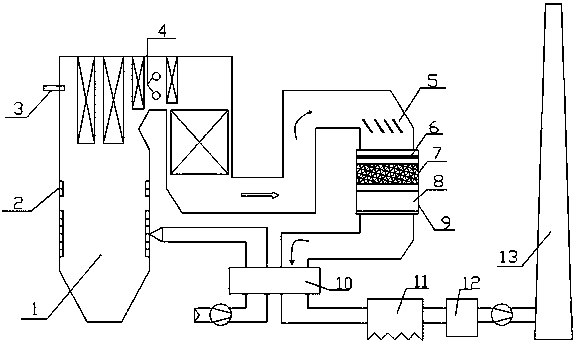
[0026] The following is a further detailed description of the multi-stage pyrolysis coupling denitrification method with a pre-flow field uniform device according to the accompanying drawings and specific examples.

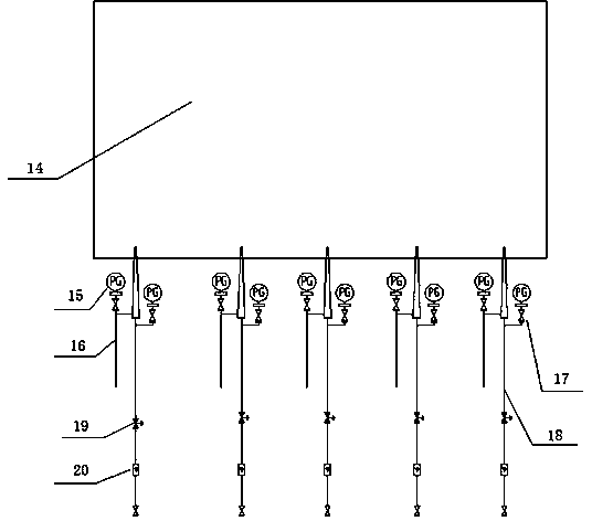
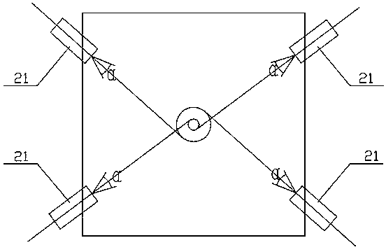
[0027] Such as Figure 1 to Figure 3 As shown, in the invented multi-stage pyrolysis coupling denitrification device, a pre-flow field uniform device is provided on the boiler furnace, more than one layer of reducing agent ammonia replenishment spray guns are fixedly arranged on the boiler front wall, and a boiler horizontal flue is arranged Ammonia supplementation spray gun for reductant above the first floor, and SCR reactor with SCR catalyst fixedly installed at the tail flue of the boiler. As a preferred solution of the present invention, the front flow field uniform device is a swingable tuyere arranged on the furnace of the boiler. In particular, it is preferable that the reducing agent ammonia replenishing spray gun 3 is arranged at the position where the ...


PUM


Abstract

The invention discloses a multi-stage themolysis coupled denitration method using a front flow field uniformizing device and a device thereof. In the method, the uniformity of NOx in the cross section of a furnace hearth is optimized by mounting the front flow field uniformizing device, different numbers of reducer ammonia supplying spray guns are arranged in different modes at different positions in flues with different flue gas temperatures of a boiler to make NOx and NH3 uniformly distributed correspondingly; and an semiconductor control rectifier (SCR) reactor containing an SCR catalyst is arranged in a tail flue of the boiler. In the invention, the comprehensive denitration efficiency reaches over 90 percent, the consumption of SCR catalyst is reduced, the consumption of a reducer is reduced by improving the reducer utilization rate of selective non-catalytic reduction reaction areas, and escape of ammonia is controlled effectively; and the improvement on the conventional boiler denitration engineering is easy, and the method and the device are applicable to various boiler and industrial kiln furnaces and have a bright application prospect.

Description

technical field [0001] The invention relates to a coal-fired boiler pollutant discharge control method and a device thereof, in particular to a multi-stage pyrolysis coupling denitrification method with a pre-flow field uniform device and a device thereof. Background technique [0002] Nitrogen oxides NOx including N 2 O, NO, NO 2 , N 2 o 3 , N 2 o 4 and N 2 o 5 , is considered to be one of the main sources of air pollution. where NO and NO 2 It is an important air pollutant, and the nitrogen oxides produced in the combustion are almost all NO and NO 2 . 70% of my country's total nitrogen oxide emissions come from direct combustion of coal, and the power industry is a large coal-burning household in my country, so the main source of NOx emissions is thermal power plants. The increasingly stringent environmental regulations require that NOx emission reduction methods be applied to NOx emission sources, especially power plant boilers, in order to control the total e...

Claims


Application Information

Patent Timeline
Patent Type & Authority Patents(China)
IPC IPC(8): B01D53/90B01D53/56
Inventor 周昊岑可法胡善涛陈丰殷红
Owner ZHEJIANG UNIV
Why Eureka
Try Eureka