
Upper-layer paddle for high-performance agitating tank

A stirring tank and high-performance technology, applied in the field of upper-layer paddles, can solve problems such as increased energy consumption, and achieve the effects of increased scouring force, enhanced stirring intensity, and strong stirring performance

Inactive Publication Date: 2012-07-04
SHENYANG ALUMINIUM MAGNESIUM INSTITUTE
View PDF4 Cites 2 Cited by
  • Summary
  • Abstract
  • Description
  • Claims
  • Application Information

AI Technical Summary

Problems solved by technology

That is to say, there must be enough blade layers, so the energy consumption increases

Method used


Image

  • Upper-layer paddle for high-performance agitating tank
  • Upper-layer paddle for high-performance agitating tank
  • Upper-layer paddle for high-performance agitating tank

Examples


Embodiment Construction

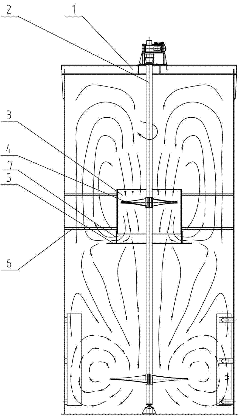
[0015] Attached below figure 2 The present invention is described in further detail.

[0016] Such as figure 2 The upper paddle of the high-performance stirring tank shown includes the paddle 4, and the outer circle of the paddle 4 is provided with an upper steel plate cylinder 3, and an annular baffle 5 is arranged under the upper steel plate cylinder 3, and the upper steel plate cylinder 3 and the stirring tank The side walls of 1 are connected by support plates 6, the upper steel plate cylinder 3 is cylindrical or conical, the diameter of the upper steel plate cylinder 3 is 1.02-1.1 times the diameter of the blade, and the height of the upper steel plate cylinder 3 is Equal to the diameter of the paddle 4, the paddle 4 is located at the upper 1 / 3 of the upper steel plate cylinder 3, the annular baffle 5 is fixed to the upper steel plate cylinder 3 through the connecting plate 7, and the distance between the annular baffle 5 and the upper steel plate cylinder 3 It is 1 / 4...


PUM


Abstract

The invention relates to an upper-layer paddle, in particular to an upper-layer paddle for a high-performance agitating tank, which is suitable for agitating devices for various agitating tanks in the alumina industry. The upper-layer paddle comprises blades, wherein the outer circle of the blades is provided with a circle of upper-layer steel plate cylinder, a ring baffle is arranged below the upper-layer steel plate cylinder, and the upper-layer steel plate cylinder is connected with the side wall of the agitating tank through a support plate. The invention has the following advantages: the upper-layer paddle provided by the invention has a good agitating effect; the upper-layer steel plate cylinder forms a collector for centralizing the liquid flows generated by an agitating paddle to one direction, so that the flow rate is accelerated, the scouring force is greatly increased, and the agitating strength is enhanced; by the ring baffle below the upper-layer steel plate cylinder, the liquid flow overflowing from the lower end of the upper-layer steel plate cylinder turns upwards after being in contact with the ring baffle, so that the effective agitating range of the upper-layer paddle is greatly expanded; a fewer number of layers of blades can meet the requirement for the agitating uniformity, so that the energy consumption is lowered; and an appropriate interval is kept between the ring baffle and the lower end of the collector, so that the energy consumption can be lowered and the cutting on liquid flows can be reduced.

Description

technical field [0001] The invention relates to an upper layer paddle, in particular to a high-performance stirring tank upper layer paddle, which is suitable for various stirring tank stirring devices in the alumina industry, and is especially aimed at the seed division tank stirring device with higher uniformity requirements. It has high mixing uniformity, low energy consumption and low shear. Background technique [0002] At present, in the production process of alumina hydrometallurgy, such as figure 1 All kinds of stirring tanks shown in the table adopt central drive paddle stirring device. When working, the central shaft drives the stirring paddle to rotate, and the blade of the stirring paddle forms an included angle with the horizontal rotating surface. When the blade rotates horizontally, it produces two component forces on the liquid flow in the horizontal circumferential direction and the vertical axial direction, and at the same time, the rotary motion of the l...

Claims


Application Information

Patent Timeline
Patent Type & Authority Applications(China)
IPC IPC(8): B01F7/20B01F27/906
Inventor 张超
Owner SHENYANG ALUMINIUM MAGNESIUM INSTITUTE
Learn More