Novel water pipe structure for high voltage direct current converter valve

A high-voltage direct current, converter valve technology, applied in output power conversion devices, electrical components, cooling/ventilation/heating transformation and other directions, can solve problems such as excessive flow of water joints, small resistance of water cooling system, large temperature difference, etc. , to achieve the effect of reducing the possibility of corrosion and leakage, reducing water flow and reducing flow resistance

Active Publication Date: 2011-08-24
CHINA ELECTRIC POWER RES INST +1
View PDF5 Cites 11 Cited by
  • Summary
  • Abstract
  • Description
  • Claims
  • Application Information

AI Technical Summary

Problems solved by technology

However, the temperature difference between the water outlet and the water inlet is relatively large, especially the last cooling element works at a higher temperature, and the water cooling system has a small resistance due to the large cross-sectional area of ​​the pipe.
In order to improve the heating condition of the end components of the cooling circuit and increase the water resistance, the arrangement of parallel pipelines is usually used, but at the same time it brings about too many water connections and excessive flow.

Method used


Image

  • Novel water pipe structure for high voltage direct current converter valve
  • Novel water pipe structure for high voltage direct current converter valve

Examples


Embodiment 1

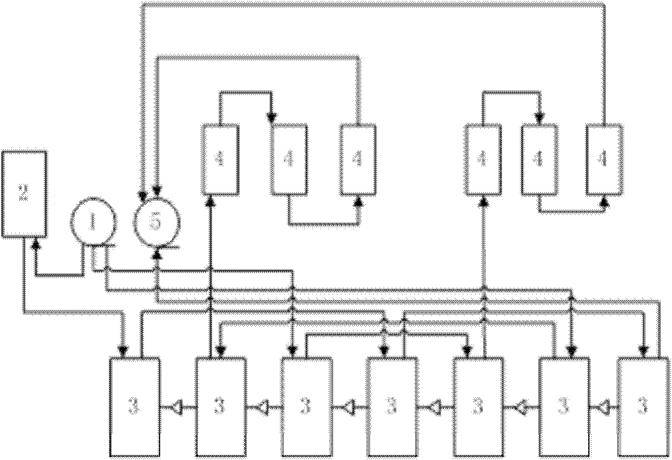
[0020] Such as figure 1 As shown, a hydraulic impact device in this example includes a water inlet 1, a saturated reactor 2, a crystal valve tube radiator 3, a damping resistor 4 and a water outlet 5, and the water pipe structure includes at least two independent cooling branches Composed in parallel, the cooling branch in this scheme includes three independent cooling branches, the first branch, the second branch and the third branch, and each independent cooling branch is connected in series, and the three independent The cooling branch uses a water inlet 1 and a water outlet 5 in common. The first branch includes the water inlet 1, the saturated reactor 2, three crystal valve tube radiators 3 and the water outlet 5, and the second branch includes the water inlet 1, Two crystal valve tube radiators 3 , three damping resistors 4 and a water outlet 5 , and the third branch includes a water inlet 1 , two crystal valve tube radiators 3 , three damping resistors 4 and a water out...


PUM


Abstract

The invention relates to the technical field of a water cooling system in power electronics, in particular to a novel water pipe structure for a high voltage direct current converter valve. The water pipe structure comprises a water inlet, a saturated reactor, a thyristor radiator, a damp resistor and a water outlet; the water pipe structure is formed by connecting three independent cooling branches of a first branch, a second branch and a third branch in parallel; and each of the independent cooling branches is connected with each other in series. In the invention, the direct current converter valve is designed into a mixed distribution way of parallel and series connection; through reasonably matching flow resistance and thermal resistance of thermal elements, under the condition of acquiring excellent heat exchange conditions, the flowing resistance of the a water system is increased a little; simultaneously, the water system has excellent electric insulated property; the number of water joints is reduced; and the leaking probability is reduced.

Description

Technical field: [0001] The invention relates to the field of water cooling systems in power electronics, and more particularly relates to a novel water pipe structure applied to high-voltage direct current converter valves. Background technique: [0002] The converter valve is the core equipment of the DC transmission project. Its design applies the latest technology of power electronics technology, light-controlled conversion technology, high-voltage technology, control technology, voltage equalization technology, cooling technology and high-voltage insulating materials. Among them, the water cooling system is an important part of the converter valve. It discharges the power consumption and heat of each component on the valve hall to the outside of the valve hall to ensure the normal operation of the thyristor. The junction temperature is within the normal range. [0003] Traditional water cooling systems are arranged in series or in parallel. The converter valve assembly...

Claims


Application Information

Patent Timeline
Patent Type & Authority Applications(China)
IPC IPC(8): H02M1/00H05K7/20
Inventor 查鲲鹏周建辉屈海涛
Owner CHINA ELECTRIC POWER RES INST
Why Eureka
Try Eureka