
Liquid crystal display device and drive method thereof

A technology of a liquid crystal display device and a driving method, which is applied to static indicators, optics, instruments, etc., can solve the problems of power consumption in the driving mode of the size design of the storage capacitor Cst that have not been mentioned, and achieve low data line voltage and screen update rate, The effect of reducing electricity

Inactive Publication Date: 2014-07-23
DONGGUAN MASSTOP LIQUID CRYSTAL DISPLAY +1
View PDF1 Cites 0 Cited by
  • Summary
  • Abstract
  • Description
  • Claims
  • Application Information

AI Technical Summary

Problems solved by technology

[0003] However, none of the above-mentioned existing designs mentioned the size design of the storage capacitor Cst and the matching driving method to save power consumption

Method used


Image

  • Liquid crystal display device and drive method thereof
  • Liquid crystal display device and drive method thereof
  • Liquid crystal display device and drive method thereof

Examples


Embodiment Construction

[0027] The aforementioned and other technical contents, features and effects of the present invention will be clearly presented in the following detailed description of the embodiments with reference to the accompanying drawings. The directional terms mentioned in the following embodiments, such as: up, down, left, right, front or back, etc., are only referring to the directions of the drawings. Accordingly, the directional terms are used to illustrate and not to limit the invention.

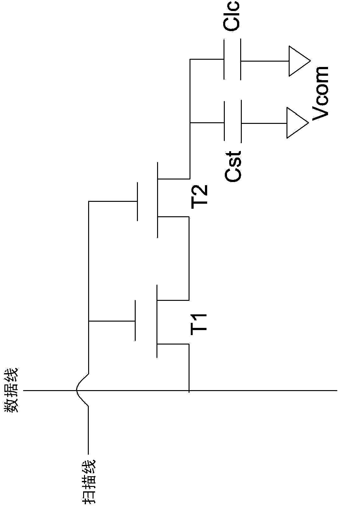
[0028] image 3 It is a schematic diagram of a reflective thin film transistor liquid crystal display according to an embodiment of the present invention. like image 3 As shown, each pixel unit of the reflective thin film transistor liquid crystal display 10 includes two thin film transistors (TFT) T1, T2 and a storage capacitor Cst. The thin film transistors T1, T2 and the storage capacitor Cst are composed of a stack structure including a first metal layer M1 and a second metal layer M2. ...


PUM

PropertyMeasurementUnit
capacitanceaaaaaaaaaa

Abstract

The invention relates to a liquid crystal display device and a drive method thereof. The liquid crystal display device comprises a plurality of pixel units, wherein each pixel unit comprises a first transistor, a second transistor, a reflection plate and a storage capacitor. The channel width-length ratios of the first transistor and the second transistor are larger than 12 / 5; the reflection plate is arranged in a position close to the transistors to reflect the environment light; and the storage capacitor is arranged in a position overlapping that of the reflection plate and the capacity thereof is larger than 1 pF.

Description

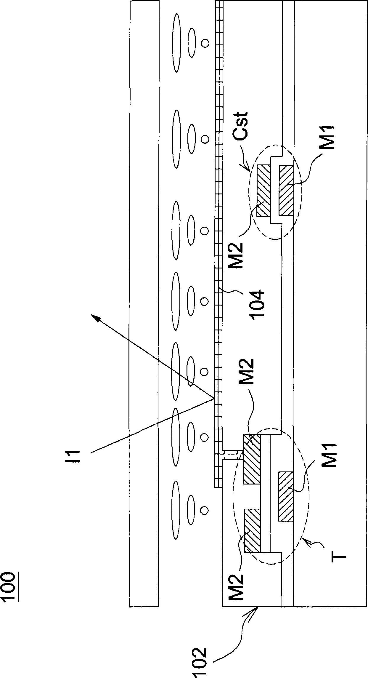
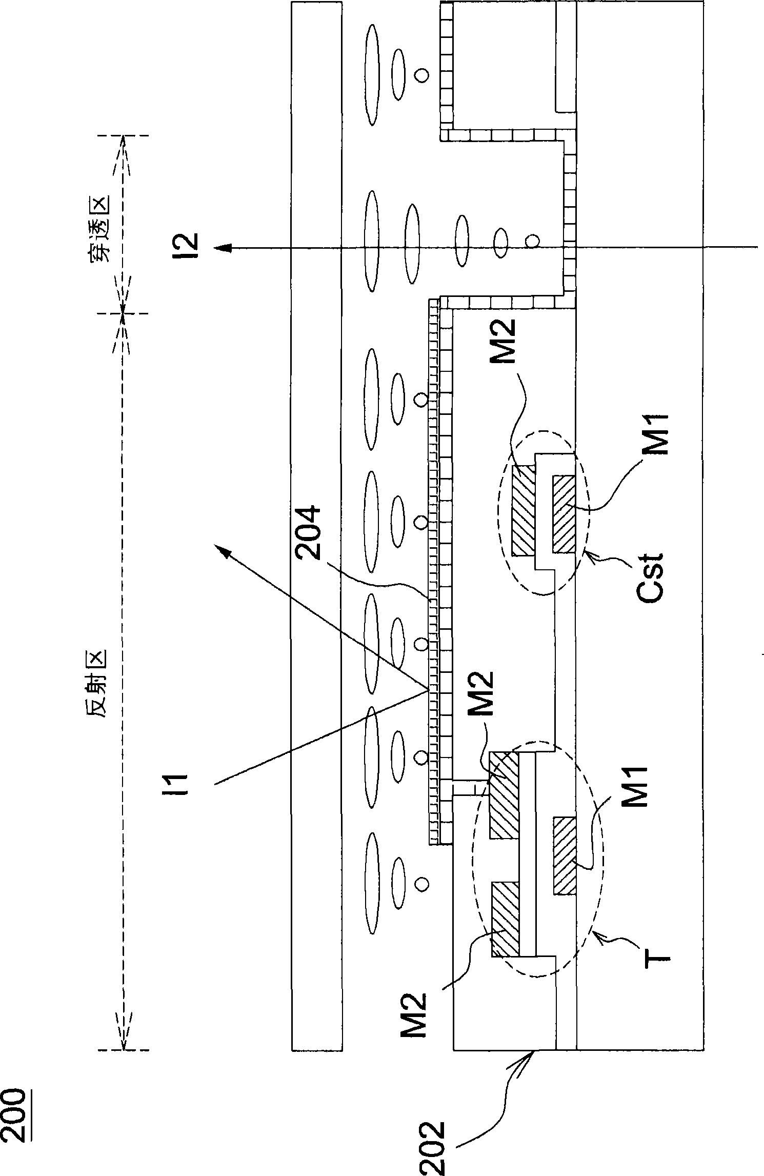
technical field [0001] The invention relates to a liquid crystal display device capable of effectively reducing power consumption and a driving method thereof. Background technique [0002] figure 1 It is a schematic diagram of a conventional reflective thin film transistor liquid crystal display (reflective type TFT LCD). like figure 1 As shown, in the reflective thin film transistor liquid crystal display 100 , the thin film transistor T and the storage capacitor Cst can be formed by using a stack structure including a first metal layer M1 and a second metal layer M2 . The reflective plate 104 disposed on one side of the array substrate 102 can reflect the ambient light I1 to save power. figure 2 It is a schematic diagram of an existing transflective type TFT LCD. like figure 2 As shown, in the transflective thin film transistor liquid crystal display 200 , each pixel area has a transmissive area and a reflective area at the same time, and the reflective area is for...

Claims


Application Information

Patent Timeline
Patent Type & Authority Patents(China)
IPC IPC(8): G02F1/1362G02F1/1368G02F1/133H01L27/02
Inventor 赖志章张迺恒王文俊王伯贤李俊贤许景富张维钧
Owner DONGGUAN MASSTOP LIQUID CRYSTAL DISPLAY
Learn More