
Electronic map matching method and device

An electronic map and matching method technology, which is applied in the field of intelligent transportation, can solve problems such as reduced accuracy, reduced computing speed, and map matching errors, and achieves the effects of reducing system calculations, increasing matching speed, and improving accuracy

Inactive Publication Date: 2011-08-10
NEC (CHINA) CO LTD
View PDF7 Cites 98 Cited by
  • Summary
  • Abstract
  • Description
  • Claims
  • Application Information

AI Technical Summary

Problems solved by technology

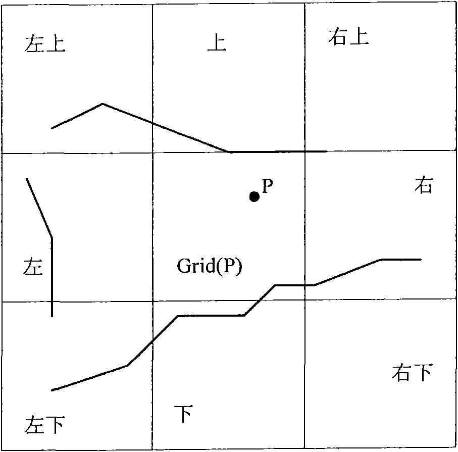
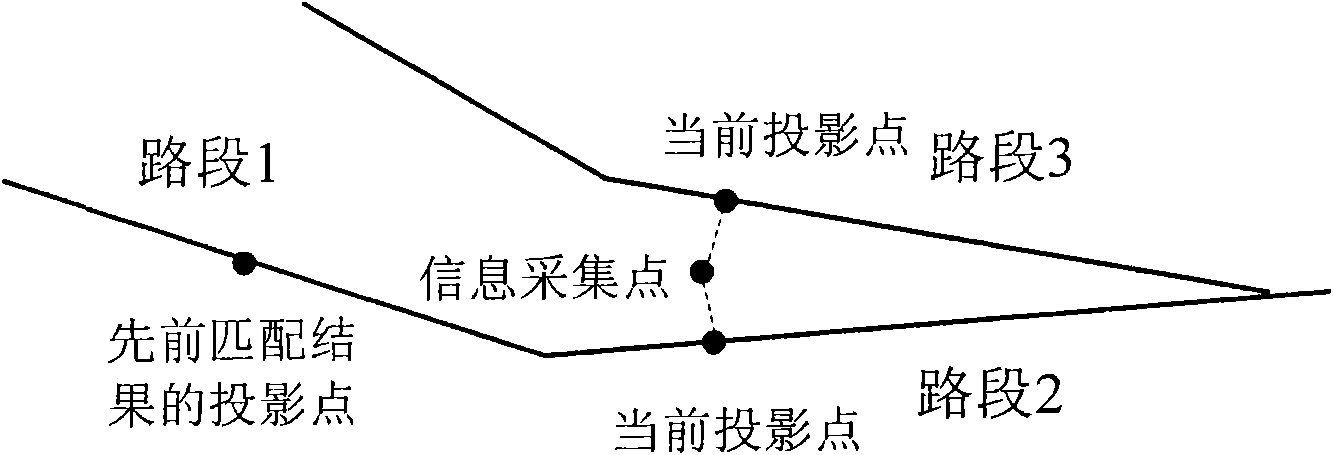
[0004] There are some defects in these traditional map matching methods, including: (1) the generation of the result of traditional map matching is just to find one or several projected points closest to the GPS point as the result of map matching through the result of projection, such The processing method does not combine the correlation between the previous matching point and the current matching result. Therefore, when the road network is relatively dense, map matching errors may occur and the accuracy will be reduced; (2) due to the small error of GPS, When searching for the grid where the GPS is located and the surrounding grids, unnecessary grids do not need to participate in the calculation, otherwise the calculation speed will be reduced, for example figure 1 As shown, the electronic map grid where the GPS point is located is Grid(P), and the GPS coordinate point P is relatively close to the upper, right and upper right grids of Grid(P), so when doing map matching, except for the above grids Except for the road information in the grid, the other grids are all invalid information
Therefore, in the traditional method, it is not necessary to search for the roads and road section information in all 9 grids in the above picture, and it will only increase the computational overhead of the system; (3) When the GPS point is located near the intersection, map matching is also very easy to occur mistake
Therefore, the accuracy of traditional map matching methods is affected by the above practices

Method used


Image

  • Electronic map matching method and device
  • Electronic map matching method and device
  • Electronic map matching method and device

Examples


no. 1 example

[0036] figure 2 Shows a schematic block diagram of an electronic map matching device according to the first embodiment of the present invention, the electronic map matching device is used to match the position of the information collection device in the geographic space at a specific moment to the electronic map, here, the information collection device can be Points represent the location of the information collection device. For example, according to practical applications, the information collection point may represent the latitude and longitude coordinates of the location of the information collection device, or other forms of location description such as text description. figure 2 The shown electronic map matching device 20 includes: a grid positioning unit 202, which locates the information collection point in the corresponding grid among the plurality of grids divided by the electronic map; a projection calculation unit 204, which projects the information collection poi...

no. 2 example

[0047] Figure 5 Shows a schematic block diagram of a map matching device 50 according to a second embodiment of the present invention, some units of the map matching device 50 and their operations are related to figure 2 The corresponding units of the shown map matching device 20 and their operations are the same, the difference is that the map matching device 50 also includes an intersection error processing unit 502, such as Figure 5 As shown, the intersection troubleshooting unit 502 may be arranged between the projection calculation unit 204 and the link grouping unit 206 . The following description of the second embodiment omits the figure 2 A detailed description of each unit shown and its operation, and using the same figure 2 the same reference signs.

[0048] The intersection error processing unit 502 in the second embodiment of the present invention is used to match the map according to the corresponding information collection point at one or more moments bef...

no. 3 example

[0053] Figure 8 Shows a schematic block diagram of a map matching device 80 according to a third embodiment of the present invention, some units of the map matching device 80 and their operations are related to figure 2 The corresponding units of the shown map matching device 20 and their operations are the same, the difference is that the map matching device 80 also includes a grid selection unit 802, such as Figure 8 As shown, the grid selection unit 802 may be arranged between the grid positioning unit 202 and the projection calculation unit 204 . The following description of the third embodiment omits the figure 2 A detailed description of each unit shown and its operation, and using the same figure 2 the same reference signs.

[0054] As above, in the first embodiment, in a manner similar to the traditional method, the projection calculation unit 204 projects the information collection points in the grid onto the road sections in the corresponding grid and its adj...


PUM


Abstract

The invention provides an electronic map matching method and an electronic map matching device for matching an information acquisition point to an electronic map. The method comprises the following steps of: a grid locating step for locating the information acquisition point in a corresponding grid in a plurality of grids divided by the electronic map; a projecting and calculating step for projecting the information acquisition point to road sections in the corresponding grid and the adjacent grid, and selecting the road section that a projecting distance meets a predetermined condition as a projecting road section; a road section grouping step for grouping each projecting road section to a preferred road section set or an alternative road section set according to matching results of the previous one or more moments; and a matching road section determining step for selecting one or more road sections that the projecting distance is less than a predetermined threshold value as a matching road section. By the invention, the position of an information acquisition device in a geographic space can be matched to the electronic map quickly and more precisely, and the correlative roads or road sections can be found precisely and quickly.

Description

technical field [0001] The invention relates to the field of intelligent transportation, in particular to an electronic map matching method and a corresponding device for matching the position of an information collection device in geographical space to an electronic map. Background technique [0002] At present, GPS technology is widely used in the field of floating cars and intelligent road traffic, and is used for real-time positioning of vehicles and providing road condition information for driving users. Due to building occlusion, satellite interference, etc., there are certain errors in the GPS positioning system, and there are also certain errors in the road network data of the electronic map. The calibration is on the electronic map. [0003] Due to the large number of floating cars in the city, and each floating car needs to send the location information of GPS technology once in a certain period, for a city, when applying the map matching method, it must be fast a...

Claims


Application Information

Patent Timeline
IPC IPC(8): G01C21/30G01C21/26
Inventor 厉程海刘晓炜胡卫松伍涛
Owner NEC (CHINA) CO LTD
Learn More