
Compound control method based on vector control system of permanent magnet synchronous motor

A technology of permanent magnet synchronous motor and compound control, which is applied in the direction of vector control system, control system, motor generator control, etc., can solve the problems of rapidity and limited anti-interference, and achieve widening of control range, good control effect, and high-efficiency data The effect of processing speed

Inactive Publication Date: 2013-02-13
SUZHOU BINGLI ELECTRIC VEHICLE TECH
View PDF0 Cites 0 Cited by
  • Summary
  • Abstract
  • Description
  • Claims
  • Application Information

AI Technical Summary

Problems solved by technology

At present, the permanent magnet synchronous motor (PMSM) vector control system generally adopts the speed and current double closed-loop control method, and most of the speed control uses the traditional PID controller. Although the traditional PID control has a simple principle, good robustness and stability, But the speed and anti-jamming ability are very limited

Method used


Image

  • Compound control method based on vector control system of permanent magnet synchronous motor
  • Compound control method based on vector control system of permanent magnet synchronous motor
  • Compound control method based on vector control system of permanent magnet synchronous motor

Examples


Embodiment

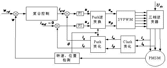
[0023] The functional block diagram of the compound control method of the opportunity permanent magnet synchronous motor vector control system described in this embodiment is as follows figure 1 As shown, firstly, each physical quantity is converted from the stationary coordinate system (three-phase stator coordinate system) to the synchronous rotating coordinate system (d, q coordinate system) by means of Clark transformation and Park transformation. This embodiment actually detects the two-phase current i a i b , through the Clark transformation, get i α i β , and then obtain the direct axis current i in the rotating coordinate system through Park transformation d and quadrature current i q As the current feedback value of the current loop for feedback comparison, while using i d The method of =0 further linearly decouples the mathematical model on the d and q axes of the permanent magnet synchronous motor. The direct axis and quadrature axis currents are compared by fee...


PUM


Abstract

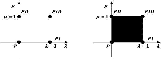
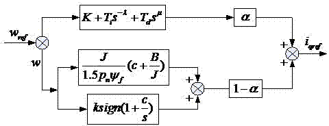
The invention discloses a compound control method based on a vector control system of a permanent magnet synchronous motor. The method comprises the following steps: converting a three-phase current of the permanent magnet synchronous motor into equivalent currents on a straight shaft and a crossed shaft by utilizing a vector conversion principle; further linearly decoupling the mathematical models of shafts d and q of the permanent magnet synchronous motor by using the method of id=0; and using fractional order PIgammaDmu control and sliding mode variable structure compound control, wherein the fractional order PIgammaDmu control and the sliding mode variable structure compound control can be used for performing joint cross-feedback control on the speed ring through a variable weighting factor alpha. The compound control method based on a vector control system of a permanent magnet synchronous motor, provided by the invention, has the advantages of both the fractional order PIgammaDmu control and the sliding mode variable structure compound control during the control of the speed ring, and the favorable factors are maximized while the unfavorable factors are minimized. Compared with the traditional PID (proportional-integral derivative) control, the fractional order PIgammaDmu control has a widened control scope, thereby more flexibly matching the sliding mode variable structure to realize the compound control to the permanent magnet synchronous motor.

Description

technical field [0001] The invention relates to the technical field of AC motor drive, in particular to a composite control method based on a permanent magnet synchronous motor vector control system. Background technique [0002] With the continuous development of the economy, automobiles have become one of the indispensable means of transportation in people's lives, and the automobile industry has become an important pillar industry of the national economy. As a green means of transportation, electric vehicles have a clear and unique banner. In recent years, consumers and governments have become more aware of environmental protection and the world's energy prices have continued to skyrocket. As a new energy vehicle with zero emissions and no pollution, electric vehicles are favored by people in the automotive industry. As the control core of the electric vehicle, the motor and its drive control system directly affect the performance of the electric vehicle. The limited sp...

Claims


Application Information

Patent Timeline
Patent Type & Authority Patents(China)
IPC IPC(8): H02P21/00H02P21/14
Inventor 雒焕强续丹曹秉刚王锋王鸣
Owner SUZHOU BINGLI ELECTRIC VEHICLE TECH
Learn More