
Section steel concrete column-steel girder node

A concrete column and concrete technology, applied in the direction of building and building structure, can solve the problems of difficult to guarantee the quality of concrete in the node area, insufficient seismic performance of the node core area, low restraint effect in the node core area, etc., so as to improve the pouring quality and improve the Constraint effect, the effect of strengthening the restraint effect

Inactive Publication Date: 2011-07-13
HARBIN INST OF TECH
View PDF6 Cites 18 Cited by
  • Summary
  • Abstract
  • Description
  • Claims
  • Application Information

AI Technical Summary

Problems solved by technology

[0003] The purpose of the present invention is to solve the problems of complex on-site construction of traditional steel concrete column-steel beam joints, difficulty in ensuring the quality of concrete in the joint area, low constraint effect of the stirrups in the joint area on the core area of ​​the joint, and insufficient seismic performance in the core area of ​​the joint, etc., to provide A type of reinforced concrete column-steel beam joint connected by steel pipe and steel beam web

Method used


Image

  • Section steel concrete column-steel girder node
  • Section steel concrete column-steel girder node
  • Section steel concrete column-steel girder node

Examples


Embodiment 1

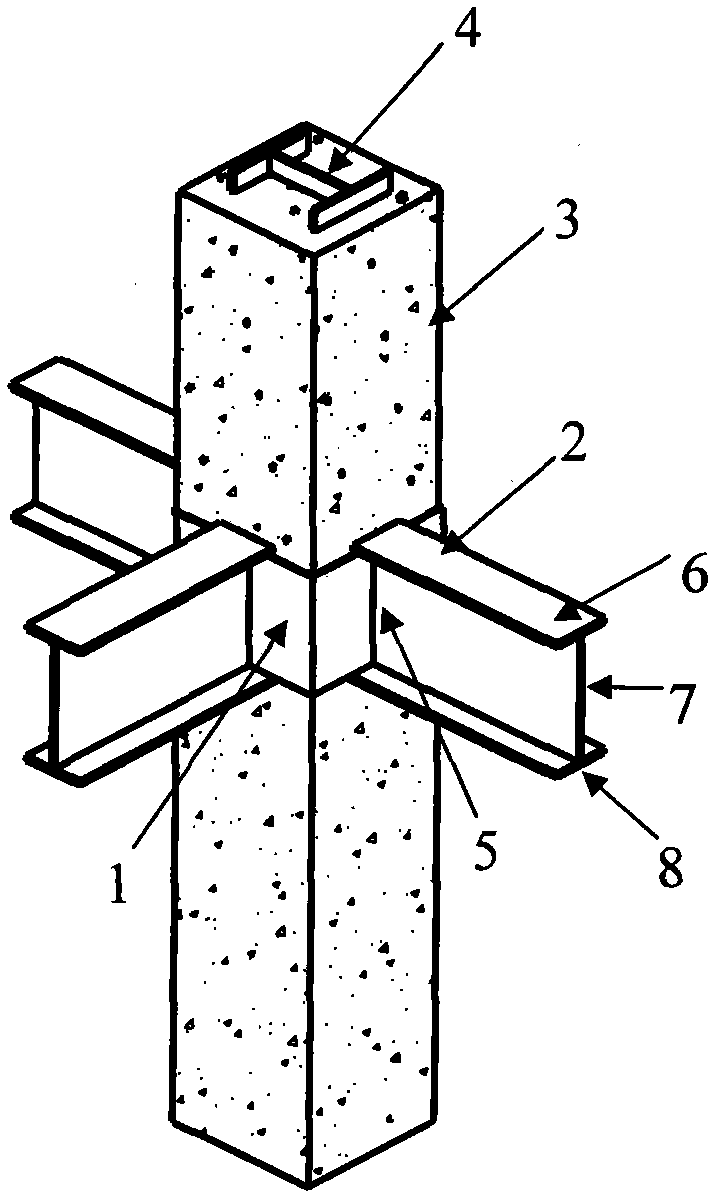
[0016] figure 1 It is the structural connection node between the circular steel pipe 1 of the present invention and the circular concrete column 3 with the steel beam 4 inside the column and the steel beam 2. Its specific structure is: the circular steel pipe 1 is partly located at the periphery of the circular concrete column 3 in the node area, The steel pipe 1 is connected to the web 7 of the horizontal steel beam 2 in the node area, and the steel pipe is located between the upper flange 6 and the lower flange 8 of the steel beam, that is, the height of the steel pipe 1 is the same as that of the steel beam web 7, and the steel pipe 1 is on the steel beam web The 7 places are disconnected and welded with the web 5 on both sides of the steel beam web 7 .

Embodiment 2

[0018] figure 2 It is the structural connection node between the rectangular steel pipe 1 of the present invention and the rectangular concrete column 3 with the steel beam 4 inside the column and the steel beam 2. The connection structure of the horizontal steel beams in the district is the same as that in Embodiment 1.

[0019] When the steel pipe in the node area of ​​the present invention is a rectangular or circular steel pipe, it can be divided into finished steel pipes, or formed by cold bending or welding of steel plates;

[0020] The steel girder in the node area of ​​the present invention can be welded or rolled I-beam or H-beam;

[0021] The profiled steel in the concrete column in the node area of ​​the present invention can adopt welded or rolled profiled steel, and the section of the profiled steel can be H-shaped steel, cross-shaped steel or T-shaped steel;

[0022] The material used for the steel pipe 1, the steel beam 3, and the steel section inside the col...


PUM


Abstract

The invention discloses a section steel concrete column-steel girder node which belongs to the technical field of building structures, solves the problem of high construction difficulty caused by field insertion of hoop reinforcement into a steel girder web plate and welding in a conventional section steel concrete column-steel girder node region. According to the technical scheme provided by the invention, the periphery of a node region section steel concrete column is provided with a steel pipe; the steel pipe is connected with the web plate of a node region horizontal steel girder; and the steel pipe is welded with the web plate on both sides connected with the steel girder web plate, so that the restriction effect of the node region is effectively enhanced and a remarkable effect is achieved. The section steel concrete column-steel girder node is a novel node form with the advantages of simple structure, convenience and quickness in constructing, capability of enhancing the concrete pouring quality of the node region, high shock resistance, high economic efficiency and high factory production degree.

Description

technical field [0001] The invention belongs to the technical field of building structures, and in particular relates to a structural connection between a steel concrete column and a steel beam. Background technique [0002] Steel concrete columns have the advantages of high bearing capacity, good seismic performance and good fire resistance, and are widely used in high-rise frame structures, high-rise frame-shear wall structures or high-rise frame-tube structures in China. However, when the steel concrete column is connected with the steel beam, stirrups must be provided in the node area to restrain the concrete, so as to ensure that the longitudinal reinforcement, steel and concrete work together. However, in the traditional steel concrete column-steel beam joint, the stirrups need to be pierced through the web of the steel beam in sections and welded at the construction site, which makes the construction difficult; and the dense stirrups also make it difficult to pour con...

Claims


Application Information

Patent Timeline
IPC IPC(8): E04B1/58
Inventor 刘界鹏周绪红甘丹郭兰慧
Owner HARBIN INST OF TECH
Learn More