
Device and method for generating all-optical arbitrary waveform based on optical fiber Bragg grating

A grating array and arbitrary waveform technology, which is applied in cladding optical fiber, optical waveguide, optical waveguide coupling, etc., can solve problems such as large loss, inability to obtain arbitrary optical pulses, and complex structure

Inactive Publication Date: 2011-07-06
TIANJIN UNIVERSITY OF TECHNOLOGY
View PDF2 Cites 12 Cited by
  • Summary
  • Abstract
  • Description
  • Claims
  • Application Information

AI Technical Summary

Problems solved by technology

Most of the current experimental research work is based on the method of "progressive" shaping of the spectrum to generate arbitrary pulse signals, such as using a diffraction grating to separate the wavelength components of the optical pulse in the spatial domain, and then modulating it with a spatial optical amplitude and phase modulator , to get the required output pulse signal, but its structure is more complicated, and the loss is also larger; the wavelength component of the optical pulse is selected by sampling fiber grating technology, and the output of a specific waveform can be obtained by changing the amplitude and phase at the same time, but not Obtain the output of arbitrary optical pulses; tap delay line filters can also be used to realize all-optical arbitrary waveform generation, but the disadvantage is that it is affected by the number of taps and phase fluctuations at the taps

Method used


Image

  • Device and method for generating all-optical arbitrary waveform based on optical fiber Bragg grating
  • Device and method for generating all-optical arbitrary waveform based on optical fiber Bragg grating
  • Device and method for generating all-optical arbitrary waveform based on optical fiber Bragg grating

Examples


Embodiment 1

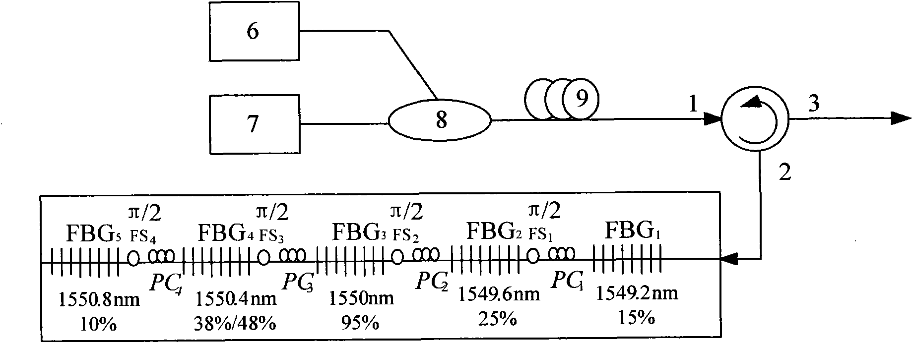
[0036] refer to image 3 , use a coupler to couple two lasers with different wavelengths, and then use the nonlinear effect in the fiber to obtain a four-wave mixing coherent light source. The frequency interval of the lasers is selected to be 50 GHz corresponding to the wavelength interval Δλ 1 0.4nm. The obtained four-wave mixing coherent light source enters the control part to complete the spectrum shaping of the coherent light source, and any optical pulse is output from the port 3 of the circulator. The central wavelength of the grating Bragg grating array is 1549.2nm, 1549.6nm, 1550nm, 1550.4nm, and 1550.8nm in sequence; the optical fiber stretcher between the gratings is controlled to produce a phase delay of π / 2, and the light wave corresponding to the central wavelength of the grating The phase difference between them is π. An optical pulse sequence with a repetition rate of 50 GHz can be obtained at the circulator 3 port. If the reflectivity of the grating array i...

Embodiment 2

[0038] refer to Figure 4 , using an electro-optic modulator to modulate a continuous wave laser with a center wavelength of 1550 nm. If the modulation frequency of the modulator is 10GHz, the wavelength interval of the corresponding grating array is Δλ 2 0.08nm. Select the center wavelength of the fiber Bragg grating array as 1549.84nm, 1549.92nm, 1550nm, 1550.08nm, 1550.16nm; the corresponding grating reflectivity is 7%, 25%, 95%, 80%, 10%; The phase delay produced by the fiber stretcher is π, π, π, π / 2 in sequence. Then a triangular wave pulse sequence with a repetition frequency of 10 GHz is obtained at the circulator 3 port, such as Figure 8 shown.

Embodiment 3

[0040] refer to Figure 5 , the supercontinuum light source contains rich frequency components, and the center wavelength of each grating in the fiber Bragg array can be freely selected and its wavelength interval can be determined. The wavelength interval Δλ of the grating Bragg grating array used 3 The center wavelength of the grating array is 1549.2nm, 1549.6nm, 1550nm, 1550.4nm, 1550.8nm; the corresponding grating reflectivity is 7%, 49.5%, 95%, 60%, 31%; The phase delay produced by the optical fiber stretcher is π, π, π, π / 2 in sequence. Obtain a rectangular pulse sequence with a repetition rate of 50GHz at the circulator 3 port, such as Figure 9 shown.

[0041] Comprehensive above-mentioned three embodiments, select different reflectivity as in embodiment 1, can improve the effect of output pulse waveform; As embodiment 1, the pulse waveform that selects different wavelength phase output in embodiment 2 is different; As implementing Example 2 and Example 3 have diff...


PUM


Abstract

The invention provides a device and a method for generating an all-optical arbitrary waveform based on an optical fiber Bragg grating. The device consists of a coherent light source and a control part; and the control part consists of circulator and an optical fiber Bragg grating array which is formed by connecting a group of optical fiber Bragg gratings, a polarization controller and an optical fiber stretcher in series. The method comprises the following steps of: inputting the coherent light source from the input end of the control part; regulating a reflection wavelength of the optical fiber Bragg grating array in the control part so as to select the wavelength of the coherent light source, regulating the reflectivity of the optical fiber Bragg grating array to control the amplitude of the coherent light source, and regulating the optical fiber stretcher to control the phase of the coherent light source; acquiring the designed all-optical arbitrary waveform in a time domain according to the Fourier transform principle and outputting by the output end of the control part. By regulating the wavelength, the amplitude and the phase of the coherent light source in a frequency domain, the output of the all-optical arbitrary waveform can be acquired in the time domain; and the device for generating a pulse waveform has a simple structure, and the method for generating the pulse waveform is easy to realize.

Description

technical field [0001] The invention relates to a device for generating all-optical arbitrary waveforms, in particular to a device for generating all-optical arbitrary waveforms based on an optical fiber Bragg grating array and a coherent light source and its working principle. Background technique [0002] In recent years, all-optical arbitrary waveform generation, as a very novel technology, has been widely used in many fields. For example, in the encoding process of the optical code division multiple access system, the amplitude and phase of the pulse frequency domain can be controlled by using the all-optical arbitrary waveform generation technology, and a low-intensity, noise-like encoding signal can be obtained; in addition, the all-optical arbitrary waveform generation technology The principle can also be extended to microwave photonic filters, and the filtering of microwave signals can be realized by controlling the phase. [0003] So far, there have been many metho...

Claims


Application Information

Patent Timeline
IPC IPC(8): G02F1/35G02B6/27G02B6/26G02B6/02
Inventor 张爱玲孙辉
Owner TIANJIN UNIVERSITY OF TECHNOLOGY
Learn More