
Portable urine analyzer

A portable urine and analyzer technology, applied in the field of urine analyzers, can solve the problem of not having claims and the like, and achieve the effect of being convenient to carry

Inactive Publication Date: 2011-07-06
北京硕泰汇丰科技有限公司 +2
View PDF14 Cites 33 Cited by
  • Summary
  • Abstract
  • Description
  • Claims
  • Application Information

AI Technical Summary

Problems solved by technology

[0014] It can be seen from the above comparative documents that none of the existing urine analyzers has all the claims of the present invention.

Method used


Image

  • Portable urine analyzer
  • Portable urine analyzer
  • Portable urine analyzer

Examples


Embodiment Construction

[0039] Below in conjunction with accompanying drawing, structure and working process of the present invention are described in detail:

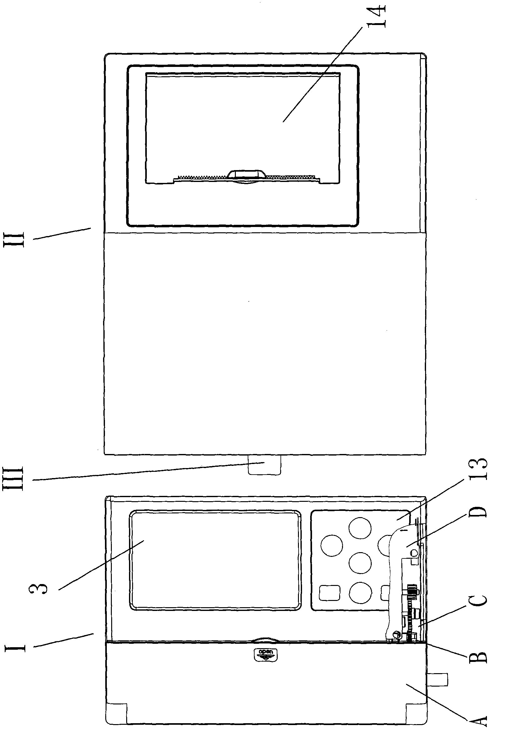
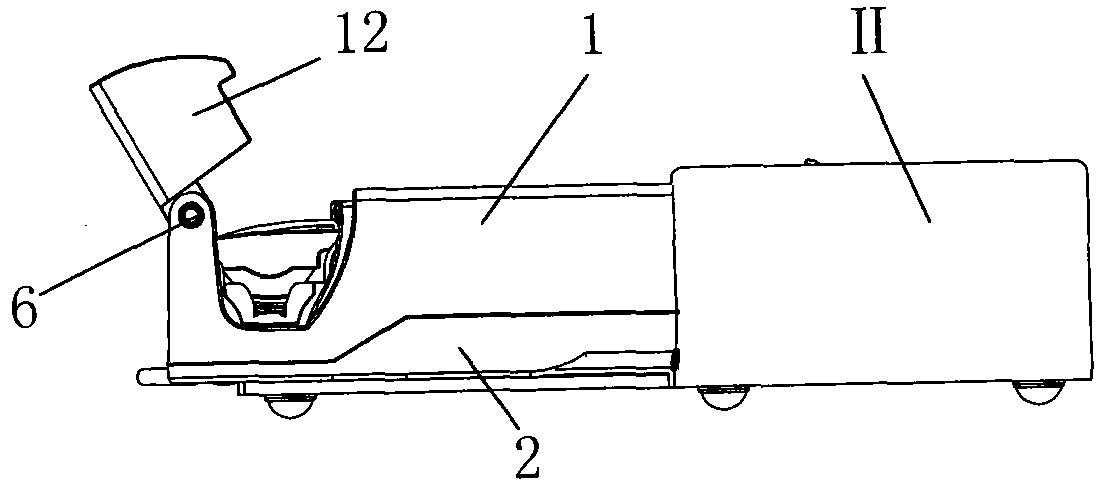
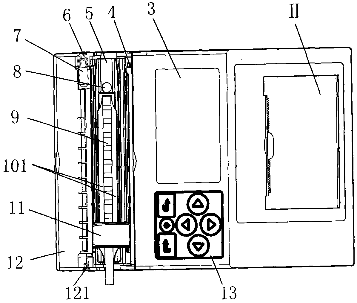
[0040] Such as Figure 1 to Figure 5 As shown, the portable urine analyzer includes two parts, the analyzer body I and the printer II, and the analyzer body I and the printer II are plugged and connected through the signal line plug connector III; the analyzer body I includes : upper box body 1, lower box body 2, on described upper box body 1, be provided with dodge door 12, LCD display 3, touch keyboard 13 and reflective optocoupler 4 for detecting whether dodge door 12 is closed, in place The lower box 2 is provided with an optical detection part A, a motor drive part B, a mechanical transmission part C, a microcomputer circuit control part D and a structural support 15, and the optical detection part A detects the urine test strip 9 , the microcomputer circuit control part D performs overall control, command sending, and result processing...


PUM


Abstract

The invention discloses a portable urine analyzer. The analyzer comprises two parts, namely an analyzer body and a printer, wherein the analyzer body is connected with the printer through a signal line connecting plug in a plugging mode; the analyzer body comprises an upper box body and a lower box body; the upper box body is provided with a movable door, a liquid crystal display (LCD), a touch keyboard and a reflecting optical coupler for detecting whether the movable door is closed; an optical detection part, a motor driving part, a mechanical transmission part, a microcomputer circuit control part and a structural bracket are arranged in the lower box body; the optical detection part is used for detecting a urine test strip; the microcomputer circuit control part is used for integral control, command transmission and result processing; the motor driving part and the mechanical transmission part are used for executing a command which is given by the microcomputer circuit control part; and the printer is used for printing the final result.

Description

technical field [0001] The invention relates to a urine analyzer, in particular to a portable urine analyzer. Background technique [0002] Existing urine analyzers are compared with the following examples: [0003] Comparative document 1, the utility model with the patent number of 200420097774.2 discloses a urine analyzer, which belongs to an in vitro diagnostic instrument, and its structure is composed of a tester and a test strip box. The display screen is set on the upper surface of the casing, the power supply and the circuit board are set in the casing, the power supply and the circuit board are connected by wires, the circuit board and the display screen are connected by data lines, and the bottom of the circuit board is provided with a light emitting Tube and receiving tube, the bottom of the shell is provided with a micro switch; the test paper box is set on the bottom of the shell corresponding to the position of the light-emitting tube and the receiving tube on ...

Claims


Application Information

Patent Timeline
IPC IPC(8): G01N21/75G01N21/27
Inventor 庄晓东余向东孔燕国倪安平
Owner 北京硕泰汇丰科技有限公司
Learn More