Detection of deformation of a wind turbine blade

A technology for wind power equipment and blades, which is used in the control of wind turbines, monitoring of wind turbines, and avoiding excessive deflection of blades. , the effect of significant savings potential

Inactive Publication Date: 2011-06-22
SIEMENS AG
View PDF6 Cites 13 Cited by
  • Summary
  • Abstract
  • Description
  • Claims
  • Application Information

AI Technical Summary

Problems solved by technology

The laser distance measurement described is problematic due to the cumbersome installation work for the optimum measuring position: Assuming that the measuring position is on a stationary part of the device, the 360° monitoring of the blade curvature is ie over the entire area swept by the blade tip. Monitoring on passing circles can only be achieved with high overhead
But requires high overhead for signal or image processing
In addition, especially the system of the camera optics cannot work independently of the weather conditions

Method used


Image

  • Detection of deformation of a wind turbine blade
  • Detection of deformation of a wind turbine blade
  • Detection of deformation of a wind turbine blade

Examples


Embodiment Construction

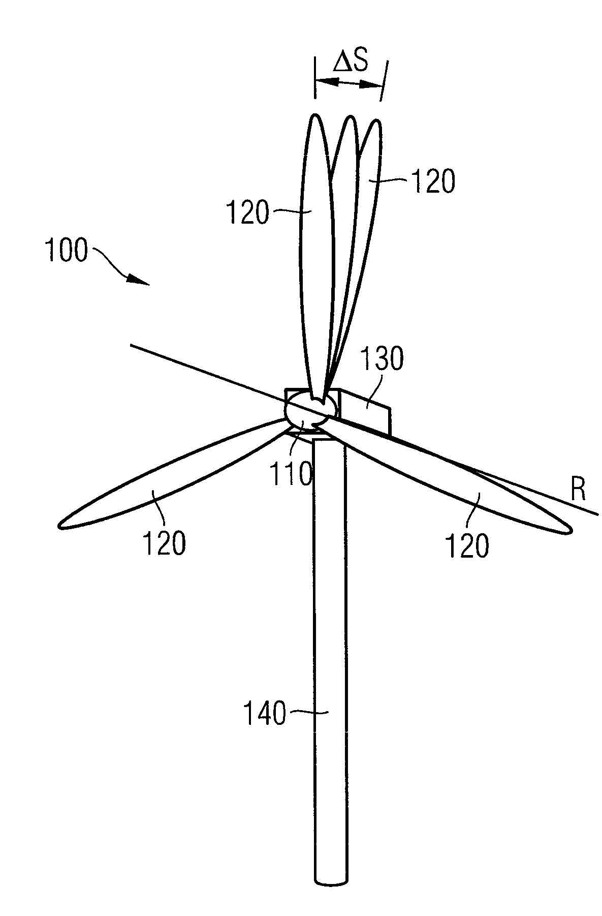
[0054] figure 1 A wind power installation 100 as known from the prior art is shown. The wind power plant 100 has a rotor 110 to which three blades 120 are fastened in the example shown. In the event of a wind load, the blades 120 are driven in a known manner, thereby setting the rotor 110 into rotation about the axis R of rotation. Furthermore, the wind power installation 100 has a nacelle 130 in which (not shown) the rotor 110 is mounted and a generator is arranged, with which the rotational energy of the rotor 110 is converted into electrical energy when a wind load occurs. (Other known components of such a wind power installation, such as the gangway fence etc. which are arranged outside the gondola, are not listed here in detail, but are generally assigned to the gondola 130 ). This is also well known. The nacelle 130 is fastened to a tower 140 of the wind power installation. The nacelle 130 is generally arranged rotatably about the longitudinal axis of the tower 140 o...


PUM


Abstract

An arrangement for detecting bending deflection of a wind turbine blade is provided. The arrangement for the wind turbine includes a radio transmitter and a linear antenna array assigned to the radio transmitter. The radio transmitter is mounted on the blade tip and emits a signal. The antenna array is mounted on the rotor of the wind turbine in a co-rotating manner and receives the signal. On the basis of the transit times of the signal from the rotor to the individual antennas of the array, the position of the radio transmitter relative to the array is determined. In the event of blade deflection, for example when a high wind load is present, the relative position changes which is detected by the arrangement.

Description

technical field [0001] The invention relates to the detection of deformations, in particular bending, of wind power plant blades. Background technique [0002] A typical wind power installation essentially has a tower and a rotor with a plurality of blades, for example two or three. During operation of a wind power plant, the rotor with the blades rotates, for example, depending on the prevailing wind force. A gondola is fastened to the tower, in which gondola in particular bearings for supporting the rotor and a generator for converting the corresponding rotational energy into electrical energy are located. Such devices are known. [0003] The structural size of such devices is constantly increasing. For example, modern wind power installations achieve rated powers in the single-digit megawatt range in offshore regions and use blades with lengths in the order of magnitude of more than 50 m. The greater the structural size, the greater the mechanical loads on the blades,...

Claims


Application Information

Patent Timeline
Patent Type & Authority Applications(China)
IPC IPC(8): F03D11/00F03D1/06F03D7/02
CPCF05B2270/33F03D11/00F03D11/0091Y02E10/72Y02E10/723F05B2270/17Y02E10/721F03D7/02Y02E10/722F03D17/00
Inventor R.吉尔利希J.赫特纳A.齐罗夫
Owner SIEMENS AG
Why Eureka
Try Eureka