Method for aligning metal grid line in solar cell metallization process
A technology for solar cells and metal grid lines, applied in circuits, electrical components, printing, etc., can solve the problems of losing efficiency advantages, poor repeatability, and low alignment accuracy, and achieve the effect of solving the difficulty of aligning metallized grid lines
- Summary
- Abstract
- Description
- Claims
- Application Information
AI Technical Summary
Problems solved by technology
Method used
Image

Examples
Embodiment 1
[0016] A method for aligning metal grid lines in a solar cell metallization process, the method comprising the following steps:
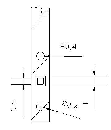
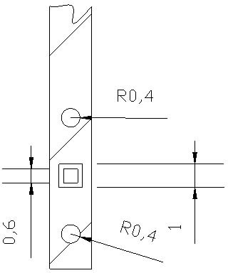
[0017] Step 1: Design a mark pattern on the four tops of the main gate design position of the silicon wafer during diffusion or other processes, and the mark pattern is a combination of two circles and a concentric square;
[0018] The width of the main grid is 1.8mm; the radius R of the circle is 0.4 mm; the side length of the inner square of the concentric square is L 1 is 0.6 mm, and the side length of the outer square is L 2 is 1 mm;
[0019] Step 2: By analyzing the mark pattern on the alignment software that comes with the Italian Baccini (Baccini) printing machine, the center position of the pattern can be accurately calculated, so that the specified area and the printed screen pattern can be accurately calculated ΔX (horizontal offset-coordinate parallel to the main grid), ΔY (longitudinal offset-coordinate perpendicular to the main grid),...
Embodiment 2
[0021] A method for aligning metal grid lines in a solar cell metallization process, the method comprising the following steps:
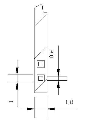
[0022] Step 1: Design a marking pattern on the four tops of the main gate design position of the silicon wafer during diffusion or other processes, and the marking pattern is a combination of two concentric squares;
[0023] The width of the main grid is 1.8mm; the side length of the inner square of the concentric square is L 1 is 0.6 mm, and the side length of the outer square is L 3 is 1 mm;
[0024] Step 2: By analyzing the mark pattern on the alignment software that comes with the Italian Baccini (Baccini) printing machine, the center position of the pattern can be accurately calculated, so that the specified area and the printed screen pattern can be accurately calculated ΔX (horizontal offset-coordinate parallel to the main grid), ΔY (longitudinal offset-coordinate perpendicular to the main grid), and Δθ (angular offset) of the center, accor...
Embodiment 3
[0026] A method for aligning metal grid lines in a solar cell metallization process, the method comprising the following steps:
[0027] Step 1: Design a marking pattern on the four tops of the main gate design position of the silicon wafer during diffusion or other processes, and the marking pattern is a combination of two circles;
[0028] The width of the main grid is 1.8mm; the radius R of the large circle is 0.8mm, and the radius R of the small circle is 0.2mm;
[0029] Step 2: By analyzing the mark pattern on the alignment software that comes with the Italian Baccini (Baccini) printing machine, the center position of the pattern can be accurately calculated, so that the specified area and the printed screen pattern can be accurately calculated ΔX (horizontal offset-coordinate parallel to the main grid), ΔY (longitudinal offset-coordinate perpendicular to the main grid), and Δθ (angular offset) of the center, according to these data, add compensation values in the pri...
PUM
 Abstract
Description
Claims
Application Information
 - R&D
- Intellectual Property
- Life Sciences
- Materials
- Tech Scout
- Unparalleled Data Quality
- Higher Quality Content
- 60% Fewer Hallucinations
Browse by: Latest US Patents, China's latest patents, Technical Efficacy Thesaurus, Application Domain, Technology Topic, Popular Technical Reports.
© 2025 PatSnap. All rights reserved.Legal|Privacy policy|Modern Slavery Act Transparency Statement|Sitemap|About US| Contact US: help@patsnap.com