
Self-adaptive multi-level radio network signal lamp system and control method thereof

A signal light system and wireless network technology, applied in the field of adaptive multi-level wireless network signal light system and its control, can solve the problems of difficulty in forming a green wave band, no lamp monitoring function, long construction period, etc., to simplify construction and electrical wiring. , flexibility and adaptability, the effect of alleviating traffic congestion

Inactive Publication Date: 2011-06-01
HEFEI UNIV OF TECH
View PDF3 Cites 26 Cited by
  • Summary
  • Abstract
  • Description
  • Claims
  • Application Information

AI Technical Summary

Problems solved by technology

[0003] Because the traffic signal controller with single-point control cannot make each intersection work together, it is difficult to form a green wave belt; while the traffic signal controller with wired network needs to excavate roads and lay pipelines, the construction period is long and the cost is high; Fully utilize the public wireless network, the communication cost is too high
Moreover, the current signal control system has no lamp monitoring function, and can only rely on inspections or road traffic police / driving reports
The current intersection signal lights are usually controlled according to several fixed timing schemes and cannot be automatically adjusted according to the traffic conditions at the intersection.
Even if there is an adaptive function, it is only an induction coil type, and the real-time and practicality are poor

Method used


Image

  • Self-adaptive multi-level radio network signal lamp system and control method thereof
  • Self-adaptive multi-level radio network signal lamp system and control method thereof
  • Self-adaptive multi-level radio network signal lamp system and control method thereof

Examples


Embodiment Construction

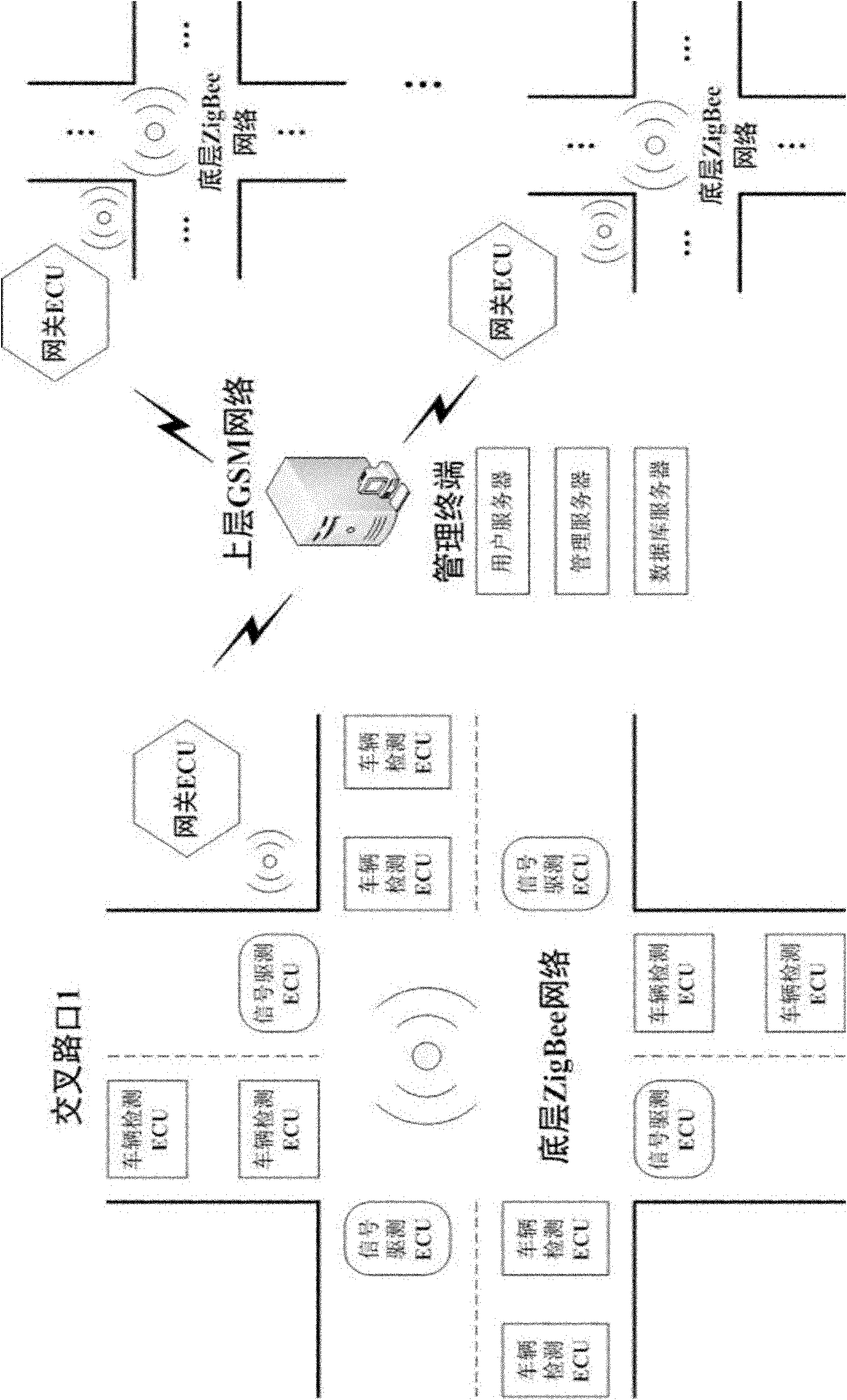
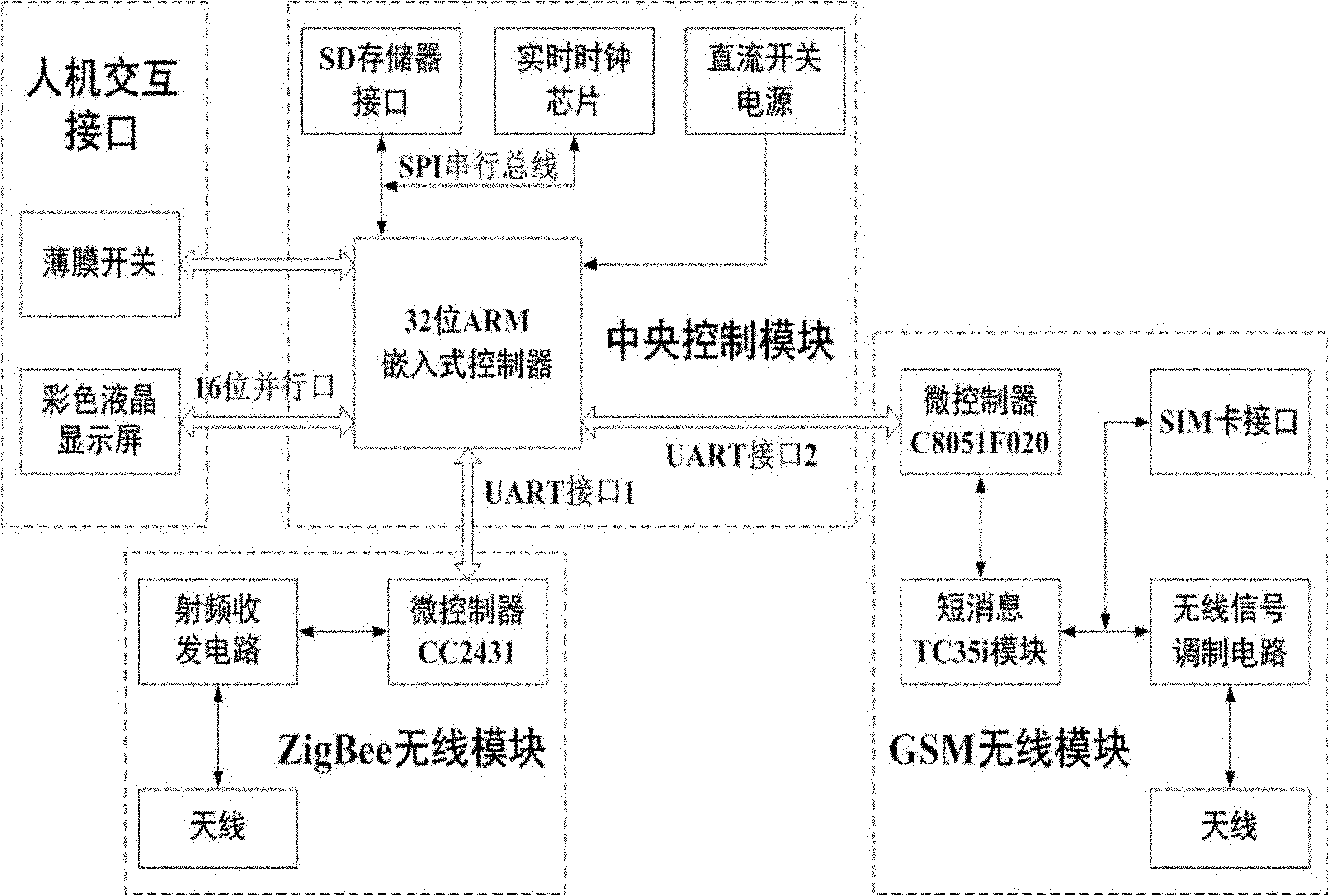
[0047] see figure 1 , the composition of the system of the present invention includes a management terminal, a gateway ECU, a signal drive test ECU, and a vehicle test ECU;

[0048] The management terminal is placed in the traffic control department, including the database server, management server, and user server, all equipped with GSM data communication interfaces, which are used for the aggregation of traffic flow information, green wave belt control, and coordinated release at multiple intersections;

[0049] The gateway ECU is set up separately at the easy-to-construction position of the intersection, which is used to complete the collection of vehicle information at the intersection, the control of the working status of the signal light, and the transmission of data between the network and the network;

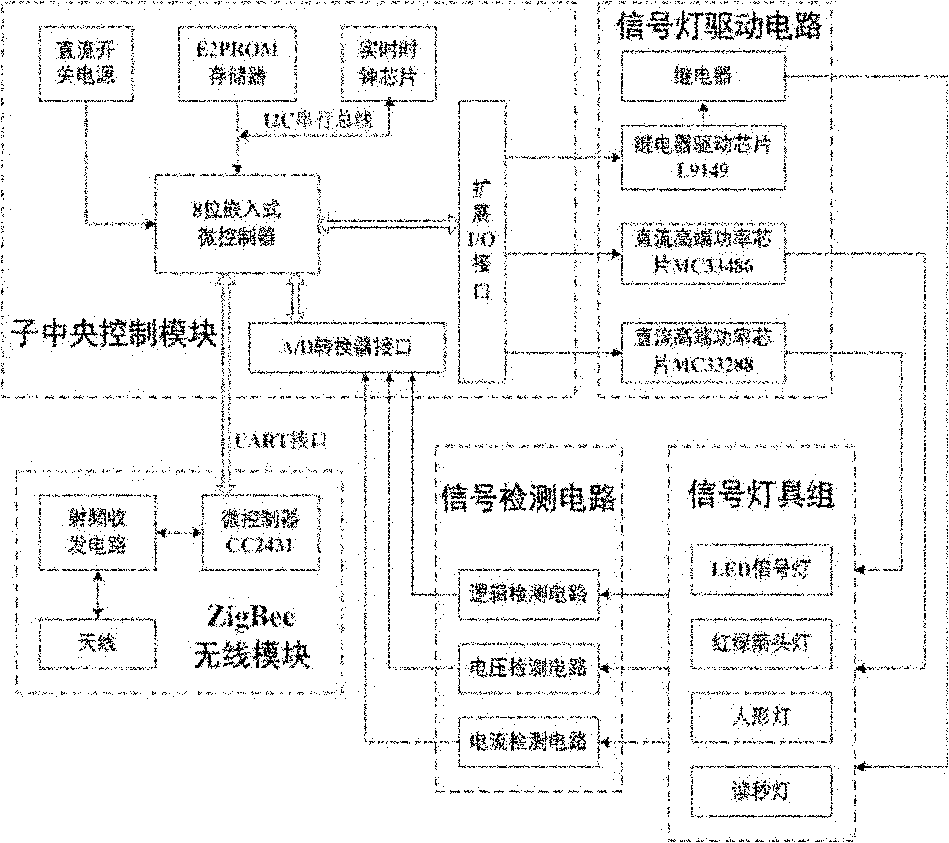
[0050] The signal driving test ECU is distributed in various signal identification forms on the side of the roadway and sidewalk in all directions, and is used to recei...


PUM


Abstract

The invention discloses a multi-level radio network-based self-adaptive signal lamp system and a control method thereof. The system is characterized by consisting of a management terminal, a gateway electronic control unit (ECU), a signal driving test ECU, and a vehicle detecting ECU; in the invention, the gateway ECU, the signal driving test ECU, and the vehicle detecting ECU arranged at each intersection are respectively taken as a coordinator, a router and a terminal node of ZigBee network for performing network and layout; the excellent characteristics of radio sensing network, such as self-organization, multi-hop routing, etc. are kept; the integral robustness, reliability and maintainability are improved; and the construction and electrical wiring are simplified. The global system for mobile communications (GSM) interface of the gateway ECU makes the management terminal and a plurality of intersections realize a green wave band coordination control function in short message internet manner. Based on a hierarchical control system of a multi-level network structure, the system can be used for handling overall traffic flow intelligence dispersion on a large scale, and has the characteristics of capability of independent running at a single intersection and keeping system intelligence even a management terminal network system fails.

Description

technical field [0001] The invention relates to an adaptive multi-level wireless network signal light system and a control method thereof, more specifically an intelligent signal light network based on upper layer GSM and bottom layer ZigBee and a control method based on the multi-level network. Background technique [0002] The currently used traffic light control system mainly adopts a single-point control mode, and each signal control machine cannot be connected with the traffic management center. A small number of traffic light signal control machines that can be networked are basically connected through wired connections. There are very few signal controllers that really use wireless networking, mainly through the general packet radio service (GPRS) or code division multiple access radio communication technology (CDMA). [0003] Because the single-point control traffic signal controller cannot make each intersection work together, it is difficult to form a green wave be...

Claims


Application Information

Patent Timeline
Patent Type & Authority Applications(China)
IPC IPC(8): G08G1/07G08G1/081G05B19/418
CPCY02P90/02
Inventor 张建军韩江洪卫星魏振春刘小平赵冲
Owner HEFEI UNIV OF TECH
Learn More