Eureka AIR delivers breakthrough ideas for toughest innovation challenges, trusted by R&D personnel around the world.

Method for simulating three-dimensional light intensity distribution of thick photoresist backside oblique incidence photoetching process

A technology of thick photoresist and light intensity distribution, used in microlithography exposure equipment, photolithography exposure devices, special data processing applications, etc., can solve the problem of inability to simulate three-dimensional light intensity distribution, and achieve high simulation accuracy Effect

Inactive Publication Date: 2011-06-01
SOUTHEAST UNIV
View PDF1 Cites 1 Cited by
  • Summary
  • Abstract
  • Description
  • Claims
  • Application Information

AI Technical Summary

Problems solved by technology

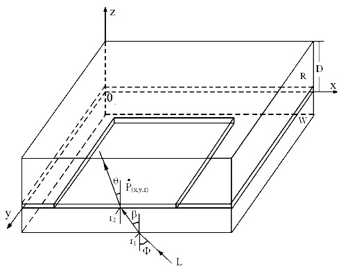
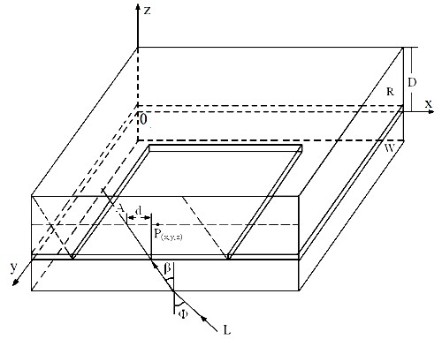
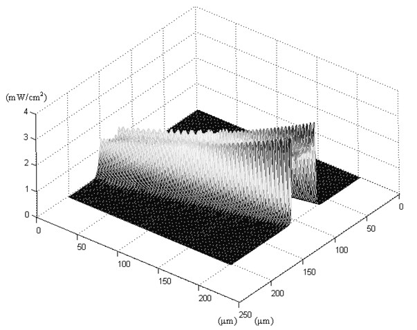
[0005]Technical problem: the purpose of this invention is to provide a three-dimensional light intensity distribution simulation method for the oblique incidence lithography process on the back of thick photoresist, so as to solve the problem that SU- 8 Problems of the three-dimensional light intensity distribution of the oblique incident back photolithography process of glue ultraviolet light

Method used


Image

  • Method for simulating three-dimensional light intensity distribution of thick photoresist backside oblique incidence photoetching process
  • Method for simulating three-dimensional light intensity distribution of thick photoresist backside oblique incidence photoetching process
  • Method for simulating three-dimensional light intensity distribution of thick photoresist backside oblique incidence photoetching process

Examples


Embodiment Construction

[0016] Based on the theory of scalar diffraction, the invention adopts the paraxial approximation technology of oblique incidence of ultraviolet light to process and simplify the Fresnel-Kirchhoff diffraction integral equation. At the same time, the reflection and refraction effects at the air / reticle and reticle / SU-8 adhesive interfaces during the propagation of ultraviolet light, as well as the absorption of ultraviolet light by SU-8 adhesive, were considered. It can quickly and accurately simulate the three-dimensional light intensity distribution inside the SU-8 glue during the oblique incident backside photolithography process of SU-8 glue ultraviolet light. The basic steps of this method are as follows: (1) According to the photolithography process conditions and parameters, input the coordinates A of the four boundary vertices of the mask hole 1(x1,y1,0) 、A 2(x1,y2,0) 、A 3(x2,y1,0) and A 4(x2,y2,0) , the incident angle Φ of obliquely incident ultraviolet light in air...


PUM


Abstract

The invention relates to a method for simulating three-dimensional light intensity distribution of thick photoresist backside oblique incidence photoetching process, which solves the problem that the three-dimensional light intensity distribution of SU-8 photoresist ultraviolet light oblique incidence backside photoetching process cannot be simulated at present. By utilizing the light intensity simulation method, the three-dimensional light intensity distribution of the SU-8 photoresist interior in the SU-8 photoresist ultraviolet light oblique incidence backside photoetching process engineering can be rapidly and accurately simulated. In the method, a paraxial approximation technology with ultraviolet light oblique incidence is utilized to process Fresnel-kirchhoff diffraction integral equation based on an optical scalar diffraction theory; upper and lower limit of the Fresnel integral is translated; a three-dimensional light intensity computation model suitable for the SU-8 photoresist ultraviolet light oblique incidence backside photoetching process is deduced; and in the three-dimensional light intensity computation model of backside oblique incidence ultraviolet light, the reflection and refraction effects on the air / mask and mask / SU-8 photoresist interface in propagation process of the ultraviolet light and absorption factor on the ultraviolet light of the SU-8 photoresist are comprehensively considered; and the three-dimensional light intensity distribution of SU-8 photoresist ultraviolet light oblique incidence backside photoetching process is high precisely simulated.

Description

technical field [0001] The invention provides a three-dimensional light intensity distribution simulation method for thick photoresist (SU-8 glue) ultraviolet light oblique incident back photolithography process, belonging to the field of computer simulation of micro-electromechanical system (MEMS) processing process. Background technique [0002] The traditional SU-8 glue UV vertical incidence lithography process can only produce vertical SU-8 glue microstructures. SU-8 adhesive UV oblique incidence lithography process can get rid of this limitation, and various inclined SU-8 adhesive microstructures can be manufactured by tilting the mask plate and SU-8 adhesive platform. However, due to the uneven thickness of the SU-8 glue during the coating process and the edge bead effect, the SU-8 glue on the edge of the substrate will be thicker than the SU-8 glue in the center of the substrate. Therefore, during the oblique incident lithography process of SU-8 adhesive UV light, th...

Claims


Application Information

Patent Timeline
Patent Type & Authority Applications(China)
IPC IPC(8): G03F7/20G06F17/50
Inventor 周再发黄庆安李伟华
Owner SOUTHEAST UNIV
Why Eureka
Eureka Blog
Learn More