
Automatic laser detector for wheel sets and method for automatically detecting wheel sets

An automatic detection and detection machine technology, applied in the detection field, can solve the problems of reducing stability and speed, high manufacturing cost, and increasing operating procedures

Active Publication Date: 2011-05-18
广西桂景计量检测有限公司
View PDF4 Cites 45 Cited by
  • Summary
  • Abstract
  • Description
  • Claims
  • Application Information

AI Technical Summary

Problems solved by technology

However, due to the measurement principle of the CCD image method used in the design, it is difficult to apply to the measurement of workpieces such as wheel sets with unclear contour boundaries, so its measurement accuracy is very low, and the displayed value varies greatly. Dozens of railway installations across the country None of the stations can be used normally
[0003] The invention patent application with the patent publication number CN101619965A, "Automatic Measuring Device for Wheelsets", applies technologies such as laser triangulation, motion control, and machine vision, and has a self-calibration function, which is used to measure train wheelsets of various specifications. Measurement of dimensional parameters; but because the detection device laser ranging sensor is installed on a three-degree-of-freedom motion mechanism, absolute measurement is performed in a fixed space seat system, and the measurement device moves on a long guide rail, so the whole machine The machining accuracy requirements are very high, and the manufacturing cost is expensive; the workpiece must be accurately positioned in the axial and radial directions of the wheel set during measurement, and the production efficiency is difficult to improve
The measurement time for each wheel set is 5 minutes, which is not suitable for the rapid repair of EMUs and the maintenance requirements of a large number of railway freight vehicles; although this patent can measure wheelsets of various gauges at the same time, this function is not suitable for railway vehicle maintenance. The site is not important, because the railway vehicles are all overhauled in a special unit, and one unit and one station only overhaul vehicles of one gauge. Although the function of adapting to various vehicles is good, the addition of movable guide rails makes the equipment more complicated. In addition, the wheel set clamping and positioning mechanism of this patent design uses the top to clamp the wheel set, and the wheels of the railway operating vehicles have shaft end covers, which cannot be clamped on this machine , therefore, it is not applicable to the detection of wheelsets of railway operating vehicles

Method used


Image

  • Automatic laser detector for wheel sets and method for automatically detecting wheel sets
  • Automatic laser detector for wheel sets and method for automatically detecting wheel sets
  • Automatic laser detector for wheel sets and method for automatically detecting wheel sets

Examples


Embodiment 1

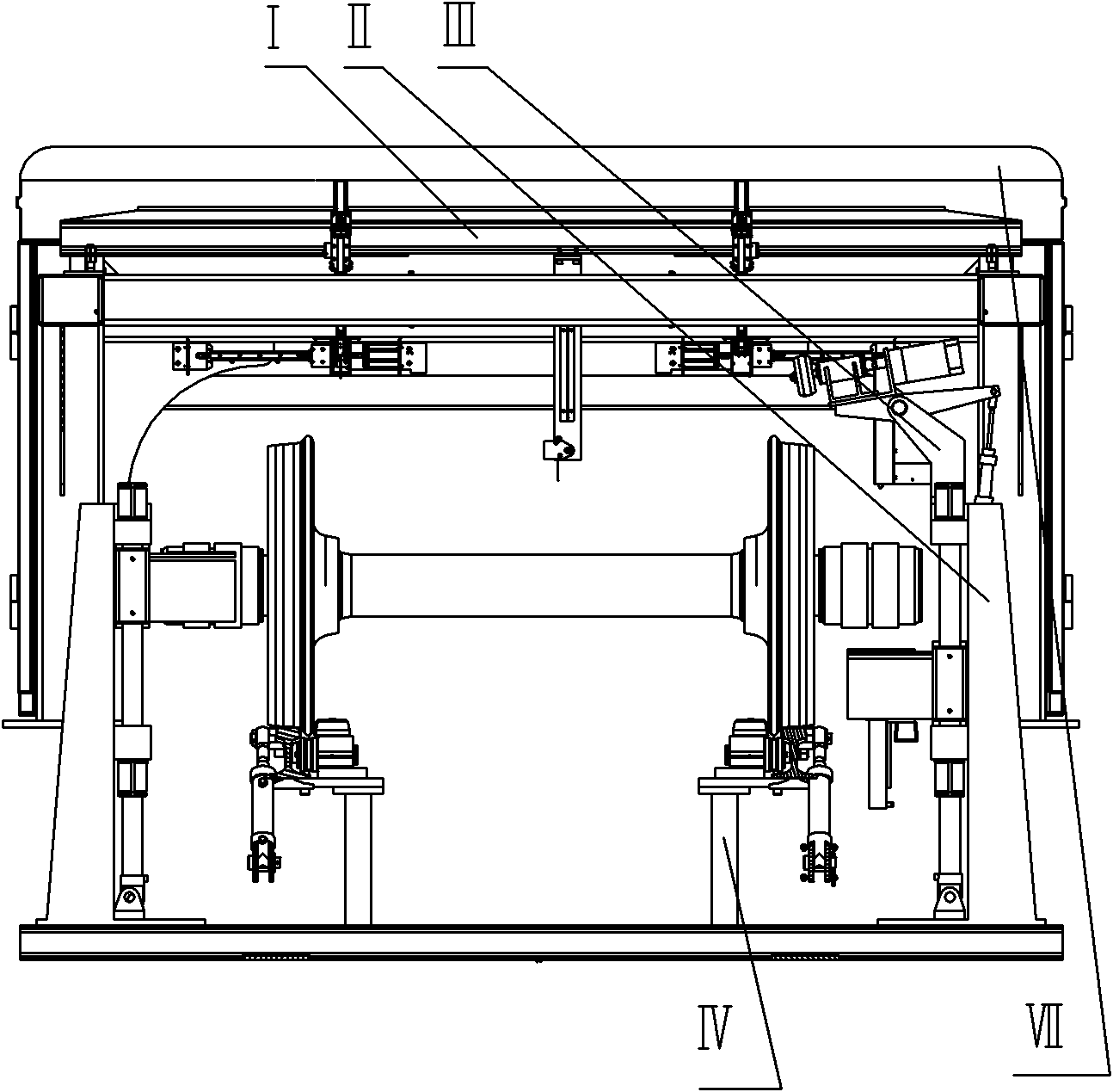
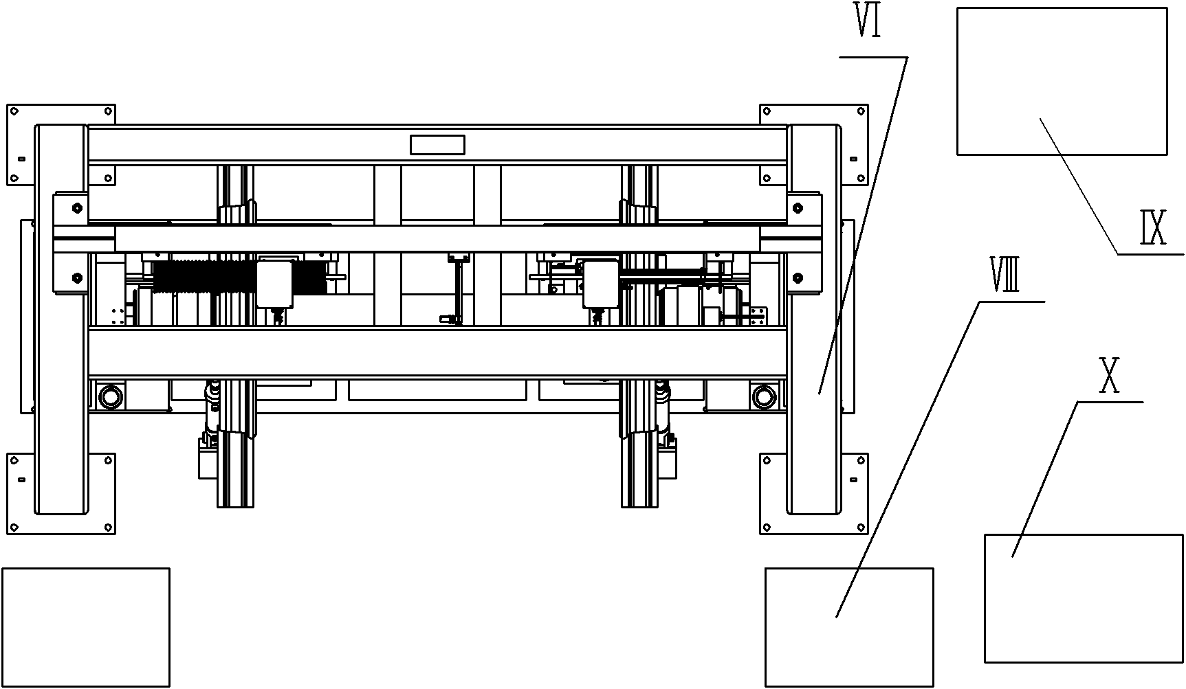
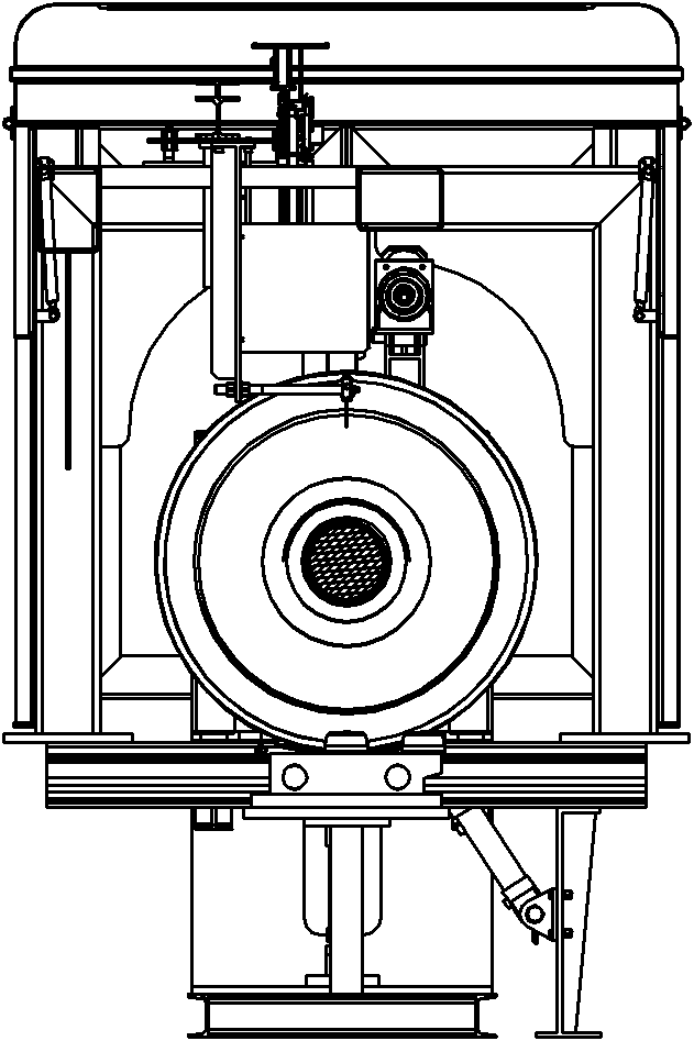
[0189] A railway wheel set laser automatic detection machine, such as Figure 1-1 to Figure 1-5 As shown, the railway wheel set laser automatic detection machine includes the wheel set measurement mechanism I, the wheel set vertical lifting mechanism II, the wheel set rotation mechanism III, the positive push and turn mechanism IV, the wheel set anti-retraction mechanism V, and the frame VI , main engine cover VII, axle identification device VIII, hydraulic system IX and operation control system X; measuring mechanism I, wheel set vertical lifting mechanism II, wheel set rotating mechanism III, forward bearing and turning mechanism IV and wheel set anti-retraction mechanism V The action is controlled by the operation control system Ⅹ, and the hydraulic system Ⅸ provides power to the oil cylinders of each mechanism.

[0190] Such as Figure 2-1 to Figure 2-3 As shown, the wheel set measuring mechanism I includes the shaft body measuring mechanism I03, the light barrier I05, the...

Embodiment 2

[0209] An automatic detection method for a wheel set, which adopts the railway wheel set laser automatic detection machine described in Embodiment 1 to automatically detect the tested wheel set, and its essence is to perform relative measurement; that is, each measuring mechanism is fixed in a spatial position, After the laser automatic inspection machine measures the standard wheel set, establish the initial value, then measure the tested wheel set to obtain the measured value, and use the following mathematical model to calculate the items of the tested wheel set using the initial value, measured value and standard parameters of the standard wheel set Parameter; the initial value can be used for a long time after one calibration.


PUM


Abstract

The invention discloses an automatic laser detector for railway wheel sets and a method for automatically detecting wheel sets by using the same. The detector comprises a wheel set measuring mechanism, a vertical lifting mechanism, a rotating mechanism, an aligning impetus-turn mechanism and a wheel set stopping mechanism, wherein the wheel set measuring mechanism comprises a shaft body measuring mechanism, a light barrier, a left wheel tread measuring mechanism and a right tread measuring mechanism; the vertical lifting mechanism comprises a base, a lifting cross beam provided with a V-shaped base, a cylinder, an upper shaft neck measuring device and a lower shaft neck measuring device; the wheel set rotating mechanism comprises a friction wheel device, a speed reduction motor, a swing arm, a pressure spring device and a wheel set rotating mechanism base; the aligning impetus-turn mechanism comprises an aligning device and a push wheel device; the wheel set measuring mechanism is arranged on a stand and is used for measuring the parameters of wheel parts of the wheel sets; and the actions of the measuring mechanism, the wheel set vertical lifting mechanism, the wheel set rotating mechanism, the aligning impetus-turn mechanism and the wheel set stop mechanism are controlled by an operation control system. The detector and the method for automatically detecting the wheel sets by using the detector have the advantages of high precision and high speed.

Description

technical field [0001] The invention relates to a detection technology, in particular to a detection technology suitable for detection of wheel tread geometry, wear, inner distance, shaft middle diameter, wheel diameter, rim thickness, rim width, rim thickness, eccentricity, etc. in the maintenance of railway vehicles. A wheel set automatic detection machine and a method for automatic wheel set detection thereof. Background technique [0002] At present, the most installed wheel set automatic detection machine in China's railways is the "wheel set automatic detection device" produced by a factory in Beijing. The distance meter constitutes the detection device, and the wheel set entry positioning and ejection mechanism is connected with the wheel set positioning mechanism and the wheel set rotation mechanism. The detection data of each area array CCD and distance meter are connected with the computer interface. However, due to the measurement principle of the CCD image metho...

Claims


Application Information

Patent Timeline
IPC IPC(8): G01B11/00
Inventor 刘显扬于中南古小灵
Owner 广西桂景计量检测有限公司
Learn More