High-efficiency heat exchanger and method for processing heat exchanger membrane

A technology of heat exchanger and processing method, which is applied in the field of energy-saving and environment-friendly air treatment equipment, can solve the problems of breeding pathogenic bacteria and microorganisms, small heat transfer area, and low heat transfer efficiency, so as to increase the area, increase the passage path, The effect of improving work efficiency

Inactive Publication Date: 2011-05-18
王光能
View PDF0 Cites 14 Cited by
  • Summary
  • Abstract
  • Description
  • Claims
  • Application Information

AI Technical Summary

Problems solved by technology

The heat exchangers currently used generally have the following three problems: (1) paper film or aluminum foil is used as the film material of the heat exchanger, the heat conduction structure is planar conduction, the heat transfer area is small, and the heat transfer efficiency Relatively low; (2) The paper film is hygroscopic, and the aluminum foil is conductive, so that the heat exchanger itself is easy to conduct electricity, and there are adverse safety hazards such as conductive leakage during use; (3) The paper film material and aluminum foil material are absorbent and Easy to oxidize, easy to breed pathogenic bacteria and microorganisms

Method used


Image

  • High-efficiency heat exchanger and method for processing heat exchanger membrane
  • High-efficiency heat exchanger and method for processing heat exchanger membrane
  • High-efficiency heat exchanger and method for processing heat exchanger membrane

Examples


Embodiment Construction

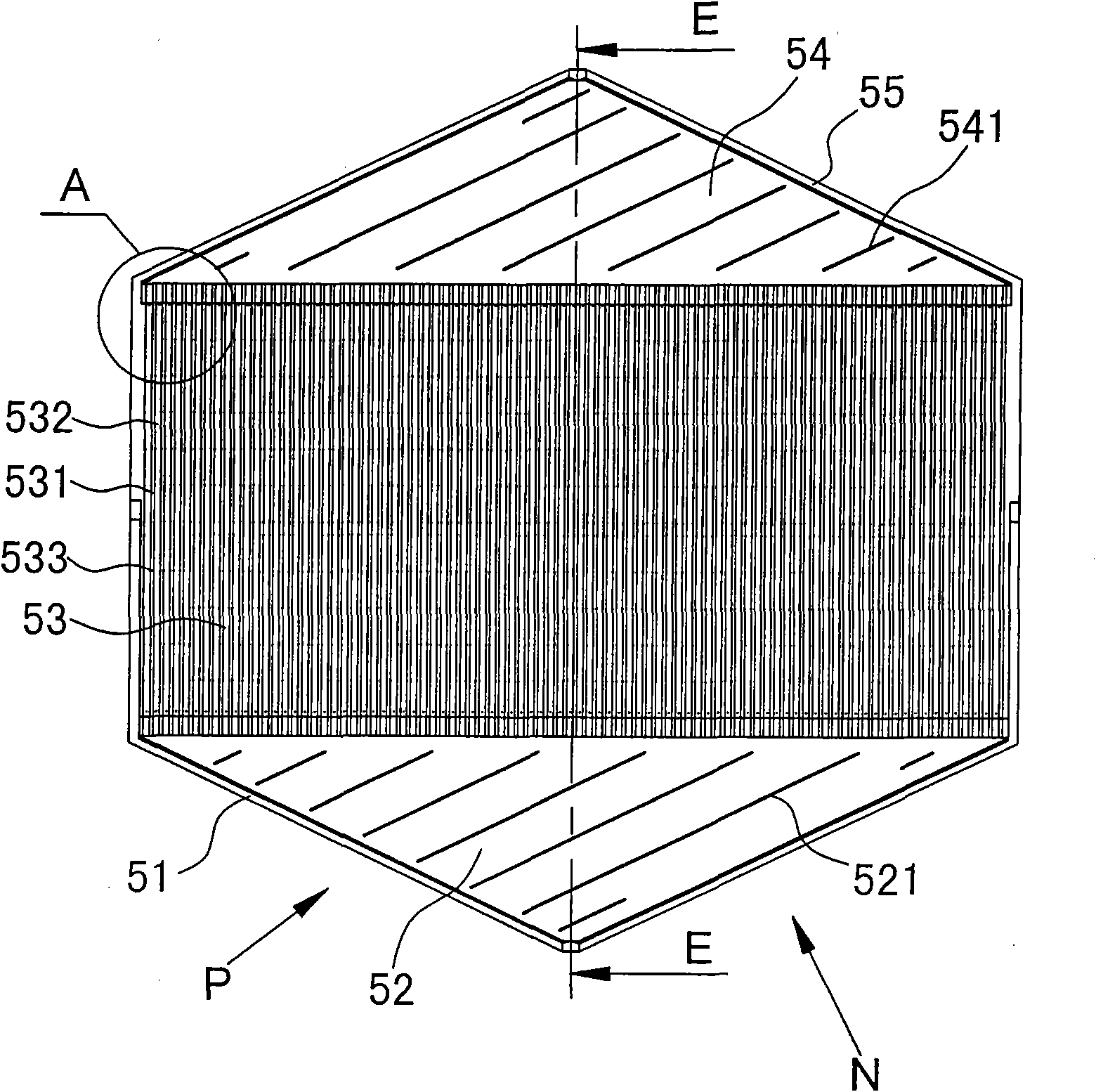
[0020] The present invention relates to high efficiency heat exchangers such as Figure 1-Figure 11 As shown, it is characterized in that it includes an upper chip 1 and a lower chip 2, and the upper and lower chips 1 and 2 are overlapped and combined. Each of them is equipped with a diversion air inlet 51, a diversion air inlet area 52, a core efficiency area 53, a diversion air outlet area 54 and a diversion air outlet 55, and the diversion air inlet 51 and the diversion air outlet 55 are arc surfaces The inlet and outlet 511, 551, the diversion air inlet area 52 and the diversion air outlet area 54 are made with induced air grids 521, 541, and the core efficiency area 53 is made with convex ridges 532, concave valleys 531 and micro Convex point 533, the flow direction of the diversion air inlet area and the diversion air outlet area intersect, and the diversion air inlet area, the core efficiency area and the diversion air outlet area form a "zigzag" air duct, which is inst...


PUM

PropertyMeasurementUnit
Widthaaaaaaaaaa
Heightaaaaaaaaaa
Horizontal lengthaaaaaaaaaa

Abstract

The invention discloses a high-efficiency heat exchanger and a method for processing a heat exchanger membrane. The heat exchanger comprises an upper chip and a lower chip, wherein the upper and lower chips are made of a membrane material through hot forming; a guide air inlet, a guide air inlet area, a core efficiency area, a guide air outlet area and a guide air outlet are formed in the upper and lower chips respectively; the guide air inlet and the guide air outlet are circular arc inlet and outlet; induction air grids are arranged in the guide air inlet area and the guide air outlet area; convex raised ridges, concave valleys and micro salient points are formed in the core efficiency area; the guide air inlet area, the core efficiency area and the guide air outlet area form an air duct in a shape like a Chinese character zhi; and baffles are arranged on two sides of the core efficiency area. The membrane material consists of a matrix and a filler, wherein the matrix is polypropylene; the filler comprises boron nitride and aluminum oxide, 0.4 weight percent of antioxidant is added into polypropylene particles, the boron nitride and aluminum oxide are mixed to form the filler according to a volume ratio of 5:2, and the matrix and the filler are mixed into aggregates according to a weight ratio of 65:35 and are subjected to hot forming.

Description

technical field [0001] The invention relates to a processing method of a heat exchanger (core body) and a membrane body of the heat exchanger, and is an energy-saving and environment-friendly air treatment device mainly used for improving and treating the air quality and heat recovery of the air-conditioning environment and the special environment of a machine room. Background technique [0002] Air treatment equipment is mainly used to improve air quality and heat recovery in air-conditioning environments and special environments in machine rooms. Its main structure includes motors, centrifugal fans, outer box shells, internal air duct structures, filters, heat exchangers, and controllers. Wait. The heat exchanger is to use the physical properties of heat conduction in the air replacement process, absorb the heat of the exhaust air, then transfer the heat to the fresh air, and send it back to the air-conditioning environment, reducing the energy consumption of the air-condi...

Claims


Application Information

Patent Timeline
IPC IPC(8): F28D9/00F28F3/08F28F21/06B29C45/00B29L31/18
Inventor 王光能
Owner 王光能
Why Eureka
Try Eureka