
Microwave thermoacoustic imaging device and method based on compressive sensing

A technology of compressed sensing and thermoacoustic imaging, which is applied in ultrasonic/acoustic/infrasonic diagnosis, sensors, and acoustic diagnosis. It can solve the problems of obvious differences in imaging effects, image artifacts, and low image resolution. 3D imaging, high resolution, the effect of enhanced resolution

Active Publication Date: 2012-09-19
HARBIN INST OF TECH
View PDF0 Cites 0 Cited by
  • Summary
  • Abstract
  • Description
  • Claims
  • Application Information

AI Technical Summary

Problems solved by technology

[0008] The purpose of the present invention is to solve the problems of complex imaging process, obvious difference in imaging effect, low image resolution, serious image artifacts and high hardware cost of the system in the existing thermoacoustic imaging technology, and provides a compressed sensing based Microwave thermoacoustic imaging device and method

Method used


Image

  • Microwave thermoacoustic imaging device and method based on compressive sensing
  • Microwave thermoacoustic imaging device and method based on compressive sensing
  • Microwave thermoacoustic imaging device and method based on compressive sensing

Examples


specific Embodiment approach 1

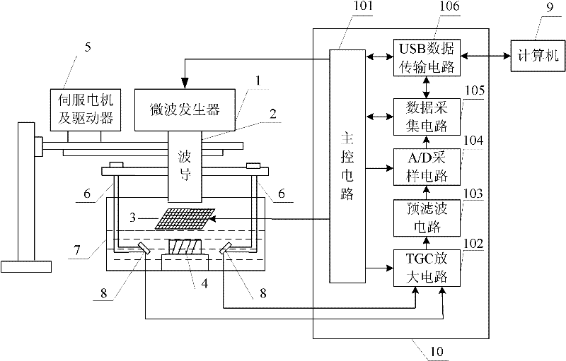
[0027] Specific implementation mode one: the following combination figure 1 Describe this embodiment, this embodiment is based on compressed sensing microwave thermoacoustic imaging device, which includes a microwave generator 1, a waveguide 2, a microwave mask 3, a servo motor and a driver 5, a bracket 6, a sample pool 7, a single array unit Ultrasonic detector 8, computer 9 and thermoacoustic signal acquisition circuit 10,

[0028] A microwave mask 3 is arranged directly above the sample cell 7, the measurement matrix output end of the thermoacoustic signal acquisition circuit 10 is connected to the input end of the microwave mask 3, and the microwave control output end of the thermoacoustic signal acquisition circuit 10 is connected to the microwave generator. 1, the pulsed microwave output by the microwave generator 1 is emitted to the surface of the microwave mask 3 through the waveguide 2, and irradiates in the sample cell 7 through the microwave mask 3,

[0029] Two si...

specific Embodiment approach 2

[0044] Embodiment 2: A microwave thermoacoustic imaging method based on a compressed sensing microwave thermoacoustic imaging device described in Embodiment 1, the method includes the following steps:

[0045] Step 1. Place the sample 4 to be tested in the center of the sample cell 7, and the built-in FPGA of the main control circuit 101 transmits a pulse signal to trigger the microwave generator 1, and at the same time controls the microwave mask 3 to generate a random matrix, and the microwave generator 1 generates a pulse Microwaves, pulsed microwaves are irradiated onto the sample 4 to be tested after passing through the waveguide 2 and the microwave mask 3 to generate thermoacoustic signals;

[0046] Step 2, the servo motor and the driver 5 adjust the observation angles of the two single-array element ultrasonic probes 8 through the bracket 6, so that the centers of the array element surfaces of the two single-array element ultrasonic probes 8 are aligned with the center o...


PUM


Abstract

The invention discloses microwave thermoacoustic imaging device and method based on compressive sensing, belonging to the technical field of thermoacoustic imaging, and aiming to solve the problems of complex imaging process, obvious imaging effect difference, low image resolution ratio, serious image artifact phenomenon and high system hardware cost in the traditional thermoacoustic imaging technology. In the invention, a microwave generator is adopted for generating pulse microwaves; the pulse microwaves are irradiated to a sample to be detected by a microwave masking film to generate a thermoacoustic signal; the thermoacoustic signal is coupled to a sound detector via ultrasound coupling liquid; two single array element ultrasonic detectors forming an angle are adopted for synchronously collecting the thermoacoustic signal; and after processing, the collected thermoacoustic signal is transmitted to a computer for image reconstruction and fusion. The microwave thermoacoustic imagingdevice comprises the microwave generator, a waveguide, the microwave masking film, a bracket, the single array element ultrasonic detectors, a thermoacoustic signal acquisition circuit and the computer. According to the invention, the single array element ultrasonic detectors are adopted for collecting the thermoacoustic signal, images are reconstructed by a compressive sensing algorithm, and hardware cost of the system is greatly lowered.

Description

technical field [0001] The invention relates to a microwave thermoacoustic imaging device and method based on compressed sensing, and belongs to the technical field of thermoacoustic imaging. Background technique [0002] Microwave thermoacoustic imaging is an imaging technology that is excited by pulse-modulated microwaves and generates ultrasound. It not only has the ability to distinguish different tissues by microwave imaging, but also combines the advantages of low price and high resolution of ultrasound imaging. It uses ultrasound probes and customized Microwave source, it is easy to achieve small portability and low cost. Microwave thermoacoustic imaging can not only provide information on the anatomical structure of the tissue, but also reflect certain physiological and biochemical characteristics (such as tissue dielectric constant, electrical conductivity, sound wave conduction law, and microwave absorbed dose, etc.). Therefore, microwave thermoacoustic imaging ma...

Claims


Application Information

Patent Timeline
Patent Type & Authority Patents(China)
IPC IPC(8): A61B8/00A61B5/00
Inventor 孙明健冯乃章沈毅李建刚马立勇伍政华
Owner HARBIN INST OF TECH
Learn More