
Method for generating cold plasma by discharge under high pressure and dielectric barrier discharge device

A technology of cold plasma and high pressure, which is applied in the field of plasma, can solve the problems of rising gas temperature, prolonging the discharge pulse time, and waste of electric energy, so as to reduce the discharge breakdown voltage and increase the discharge channel density.

Inactive Publication Date: 2011-05-11
UNIV OF SCI & TECH OF CHINA
View PDF6 Cites 6 Cited by
  • Summary
  • Abstract
  • Description
  • Claims
  • Application Information

AI Technical Summary

Problems solved by technology

An excessively large gap will prolong the discharge pulse time, easily cause spark discharge, cause the gas temperature to rise too high, and the discharge energy will be converted into gas heat energy, resulting in waste of electric energy, and the discharge will be concentrated in a small number of channels, resulting in uneven discharge distribution
[0007] In the prior art, except for the pulsed corona method, there is no method and device for generating high-density uniform cold plasma in a large space

Method used


Image

  • Method for generating cold plasma by discharge under high pressure and dielectric barrier discharge device
  • Method for generating cold plasma by discharge under high pressure and dielectric barrier discharge device
  • Method for generating cold plasma by discharge under high pressure and dielectric barrier discharge device

Examples


Embodiment Construction

[0024] The present invention will be further described below in conjunction with the accompanying drawings, without any limitation to the present invention.

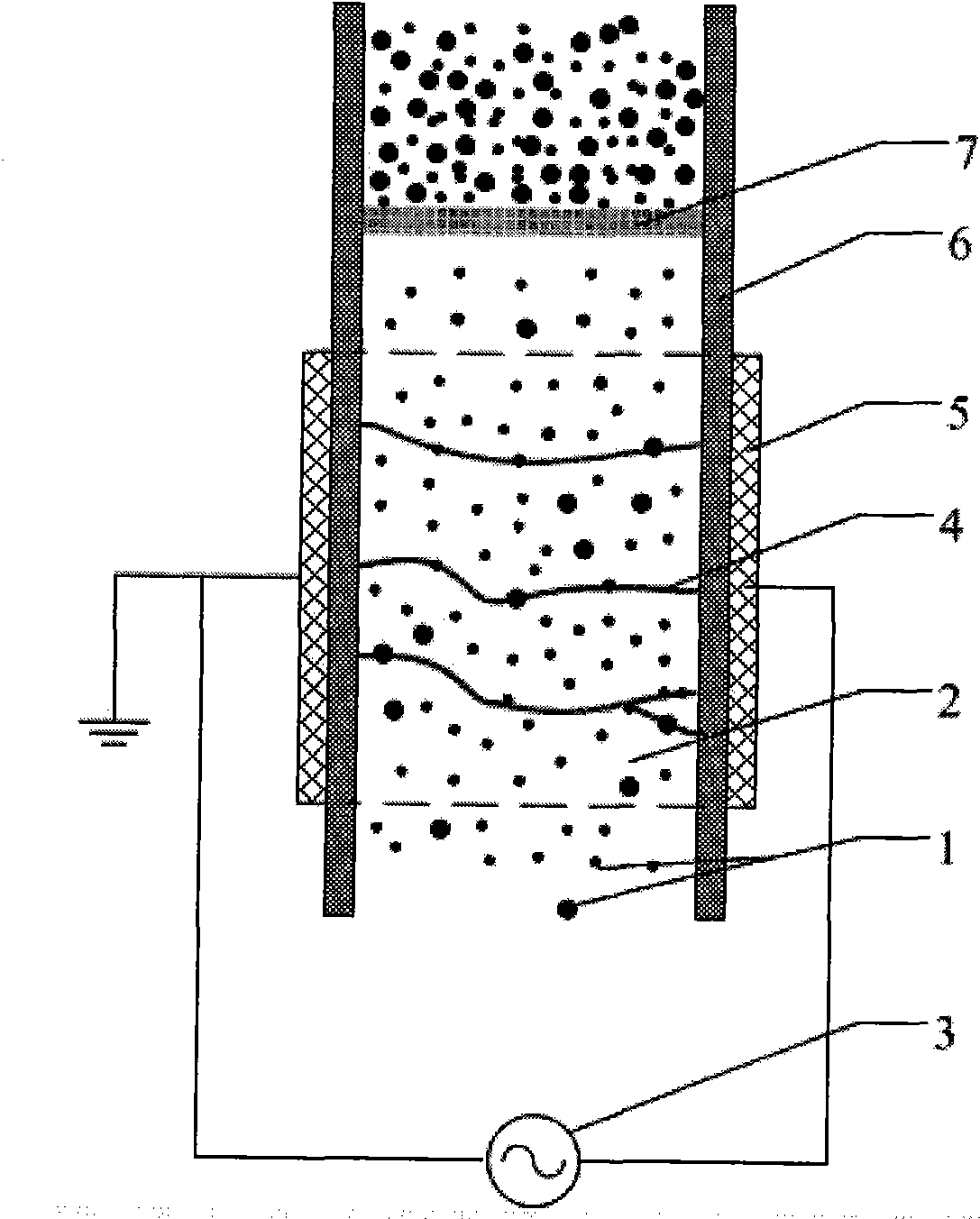
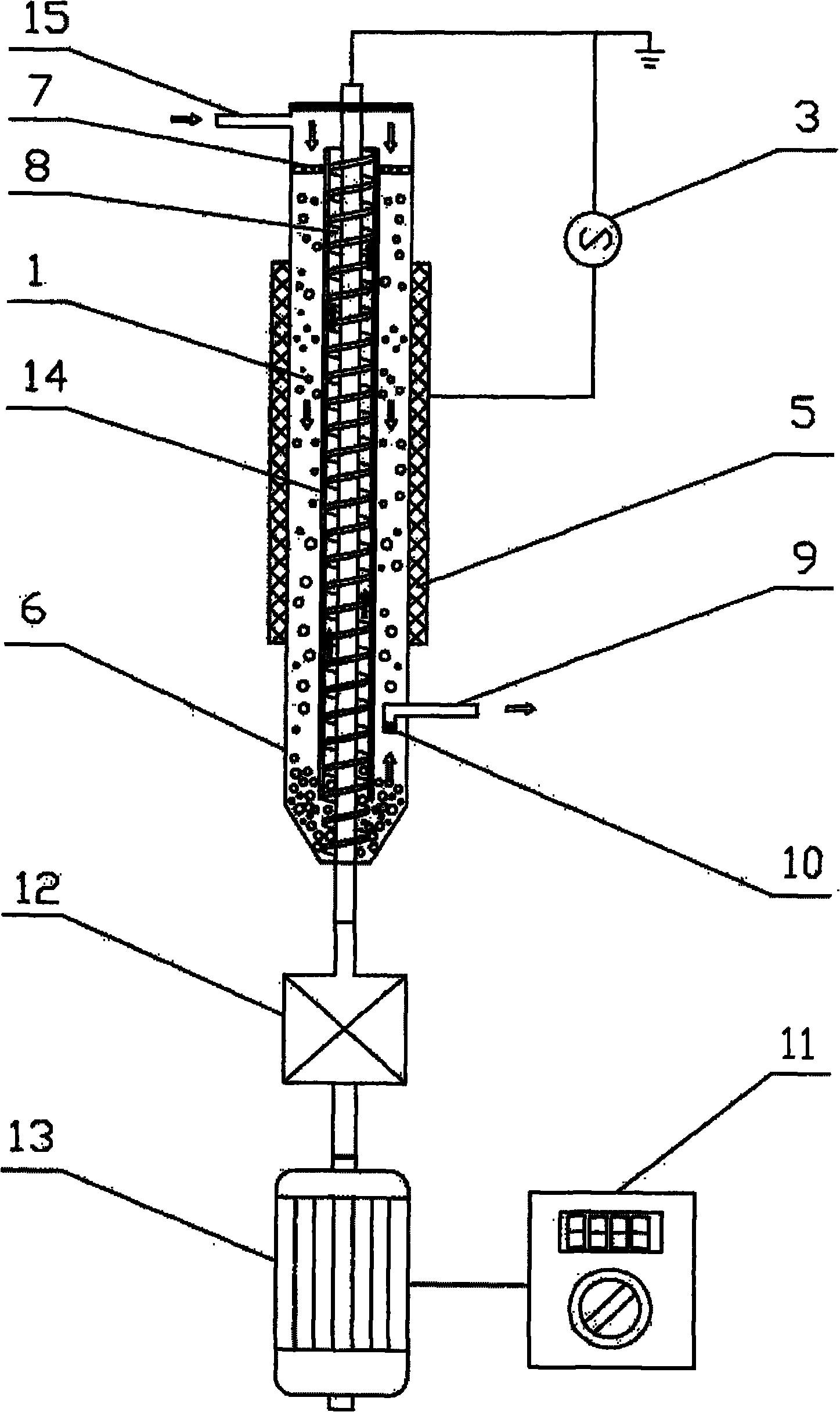
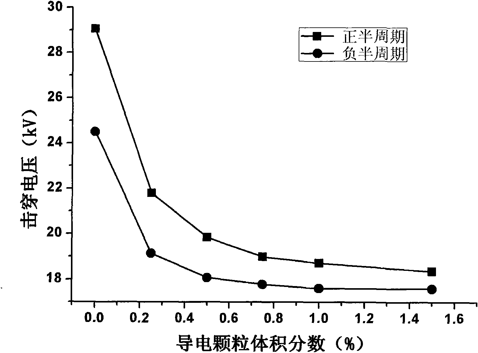
[0025] Description of drawings: figure 1 It is a schematic diagram of a dielectric barrier discharge principle device of the present invention; figure 2 It is a schematic diagram of an embodiment of the dielectric barrier discharge device of the present invention; image 3 yes figure 2 Implement the experiment result of example conductive particle (carbon powder) concentration to reduce discharge voltage effect; Figure 4 yes figure 2 Implementation example The experimental results of the effect of the concentration of conductive particles on increasing the discharge density.

[0026] figure 1 It is a schematic diagram of a dielectric barrier discharge principle device applying the above principle method. Among them, a pair of discharge electrodes 5 separated and placed in parallel, an insulating dielectric barr...


PUM


Abstract

The invention relates to a method for generating cold plasma by gas discharge under high pressure and a dielectric barrier discharge device using the method. In the method, dispersed conducting particles are added to a discharge space where an electric field is applied, the conducting particles cause electric field distortion, corona discharge firstly occurs near the conducting particle surfaces, and a discharge channel approximately develops along the leading direction of a power line. The spatial distribution evenness and density of discharge and generated cold plasma are lead by the distribution of the conducting particles. Dispersed conducting particles are added to the dielectric barrier discharge device, so that the average electric field strength applied by the discharge space is lower than the critical breakdown field strength of gas. Therefore, the discharge and the generated cold plasma are distributed more evenly in space, the voltage required by discharge can be reduced, and the invention can be widely used for various gas phase plasma chemical reactions.

Description

technical field [0001] The invention belongs to the technical field of plasma, and relates to a method and a device for generating cold plasma by gas discharge under high pressure. Background technique [0002] Active particles such as electrons, ions, free radicals, and excited atoms and molecules exist in high-pressure (usually above 0.1 atmosphere) cold plasma. Many chemical reactions that do not occur under normal conditions or can only occur under extremely harsh conditions can easily occur in high-pressure cooled plasmas. High-pressure cooled plasma is widely used in many fields of industry. [0003] Applicable methods for generating cold plasma under high pressure mainly include corona discharge and dielectric barrier discharge. In addition, discharge methods such as radio frequency, microwave, and pulsed corona can also be used. [0004] The initial discharge voltage of corona discharge is low and the electrode gap is large, but the discharge is limited near the ti...

Claims


Application Information

Patent Timeline
Patent Type & Authority Applications(China)
IPC IPC(8): H05H1/24
Inventor 夏维东周志鹏张济民叶桃红
Owner UNIV OF SCI & TECH OF CHINA
Learn More