Plasma processing apparatus
A plasma and treatment device technology, applied in the field of plasma treatment devices, can solve the problems of uneven electrode potential and current distribution, uneven plasma, etc., and achieve the effect of uniform plasma treatment
- Summary
- Abstract
- Description
- Claims
- Application Information
AI Technical Summary
Problems solved by technology
Method used
Image

Examples
no. 1 approach
[0051] First, a first embodiment of the present invention will be described.
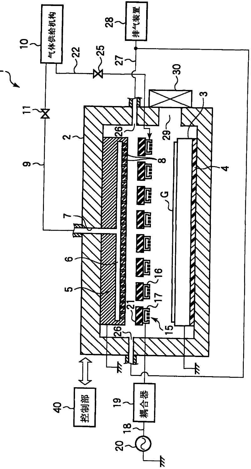
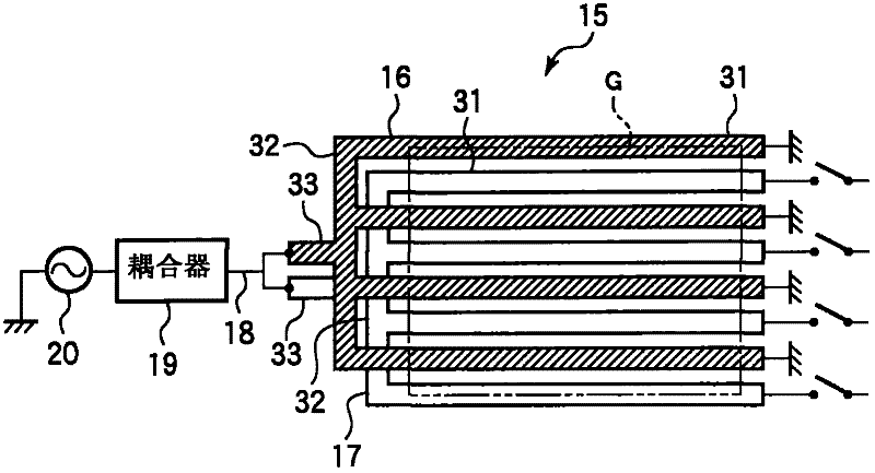
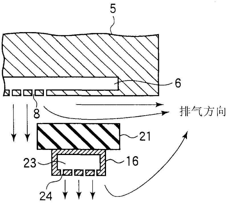
[0052] figure 1 is a cross-sectional view showing the plasma processing apparatus according to the first embodiment of the present invention, figure 2 is a plan view showing its upper electrode, image 3 It is an enlarged partial cross-sectional view showing a part of the shower head functioning as the upper electrode and the upper sealing gland.
[0053] The plasma processing apparatus 1 is configured as a sheet-type plasma processing apparatus, and has a cylindrically shaped chamber (processing container) 2 , for example, whose surface is made of alumite-treated (anodized) aluminum. A substrate mounting table (substrate supporting member) 3 for mounting (supporting) a large rectangular substrate G is provided at the bottom of the chamber 2 .
[0054] The substrate mounting table 3 is made of metal such as aluminum, and is supported on the bottom of the chamber 2 via an insulating member 4 . T...
no. 2 approach
[0079] Next, a second embodiment of the present invention will be described.
[0080] This embodiment is an embodiment in which the present invention is applied to a batch-type plasma processing apparatus that performs plasma processing on a plurality of substrates.
[0081] Figure 6 It is a cross-sectional view showing a plasma processing apparatus according to a second embodiment of the present invention. This plasma processing device 1' is a device for processing five substrates G at a time, and is compatible with figure 1The apparatus has basically the same structure as a plasma processing apparatus, and has a chamber (processing container) 51 formed of, for example, aluminum whose surface has been subjected to anodized (anodized) treatment and formed into a prismatic shape. A substrate mounting table 52 for mounting the lowermost substrate G is provided at the bottom of the chamber 51 . The substrate mounting table 52 is made of metal such as aluminum, and is supporte...
no. 3 approach
[0095] Next, a third embodiment of the present invention will be described.
[0096] Here, another example of the upper electrode is shown. Figure 7 It is a plan view showing the upper electrode in the third embodiment of the present invention.
[0097] The upper electrode 95 in this embodiment, such as Figure 7 As shown, it consists of two comb-shaped electrode parts 96 , 97 , by means of which an electrode plane is formed. These electrode members 96 , 97 are the same as the electrode members 16 , 17 of the first embodiment, and have a plurality of booklet-shaped comb teeth 31 extending in parallel at equal intervals, and one end of the plurality of comb teeth 31 passes through the connecting portion 32 Link, the other end becomes the end. In addition, a power supply portion 33 is formed on the connection portion 32 . Furthermore, these electrode members 96 and 97 are opposed to each other, and the comb teeth of the electrode member 96 and the comb teeth of the electrod...
PUM
 Abstract
Description
Claims
Application Information
 - R&D
- Intellectual Property
- Life Sciences
- Materials
- Tech Scout
- Unparalleled Data Quality
- Higher Quality Content
- 60% Fewer Hallucinations
Browse by: Latest US Patents, China's latest patents, Technical Efficacy Thesaurus, Application Domain, Technology Topic, Popular Technical Reports.
© 2025 PatSnap. All rights reserved.Legal|Privacy policy|Modern Slavery Act Transparency Statement|Sitemap|About US| Contact US: help@patsnap.com