
Pneumatic clamp for processing of claw pole outer surface

A technology of pneumatic clamps and claw poles, which is applied in the field of pneumatic clamps for external flat processing of claw poles, can solve the problems of high job assessment standards, high labor intensity, and easy edge jumping, so as to improve effective labor rate, shorten clamping time, and reduce The effect of labor intensity

Inactive Publication Date: 2011-05-11
荆州市万寿汽车零部件有限公司
View PDF3 Cites 3 Cited by
  • Summary
  • Abstract
  • Description
  • Claims
  • Application Information

AI Technical Summary

Problems solved by technology

[0002] The existing method of processing claw poles is to use ordinary lathes for processing, manual clamping, labor-intensive, and because the claw pole blank is a casting, there are defects such as blisters, pores, and surface build-up, it is generally difficult to process The turning tool of the lathe is easy to jump off the edge. After the edge is off, it needs to be re-grinded and adjusted repeatedly. The processing is time-consuming and labor-intensive, which affects production efficiency and product quality.
In addition, the operator is required to sharpen the knife after the turning tool is sharpened, which requires relatively high knife sharpening skills for the operator. The training period for new employees is long and the assessment standard is high.
Therefore, the existing processing procedures have the defect of high requirements on the operation skills of employees and the quality of blanks, which cannot make the machine tool perform at its maximum efficiency.

Method used


Image

  • Pneumatic clamp for processing of claw pole outer surface
  • Pneumatic clamp for processing of claw pole outer surface
  • Pneumatic clamp for processing of claw pole outer surface

Examples


Embodiment Construction

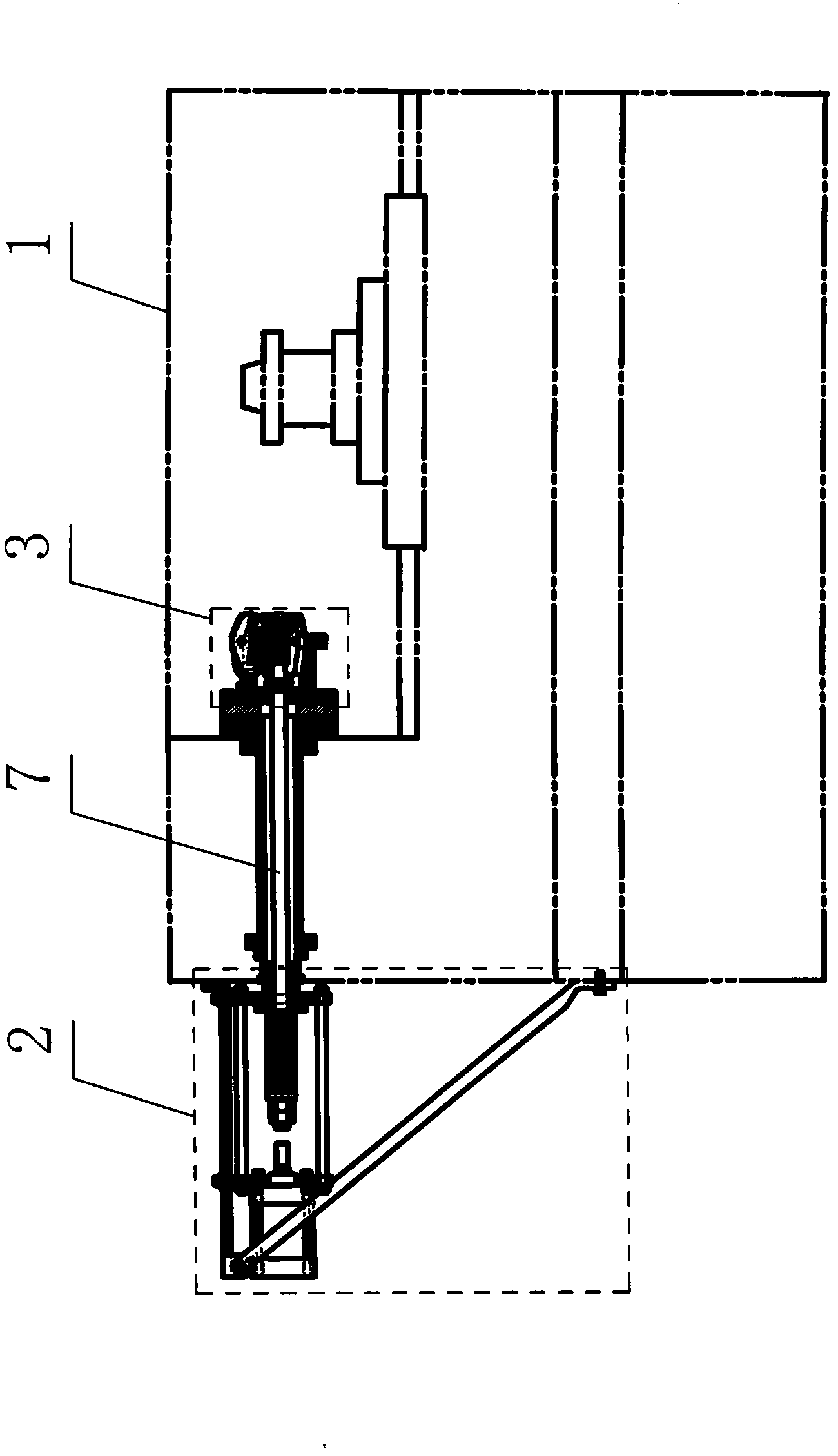
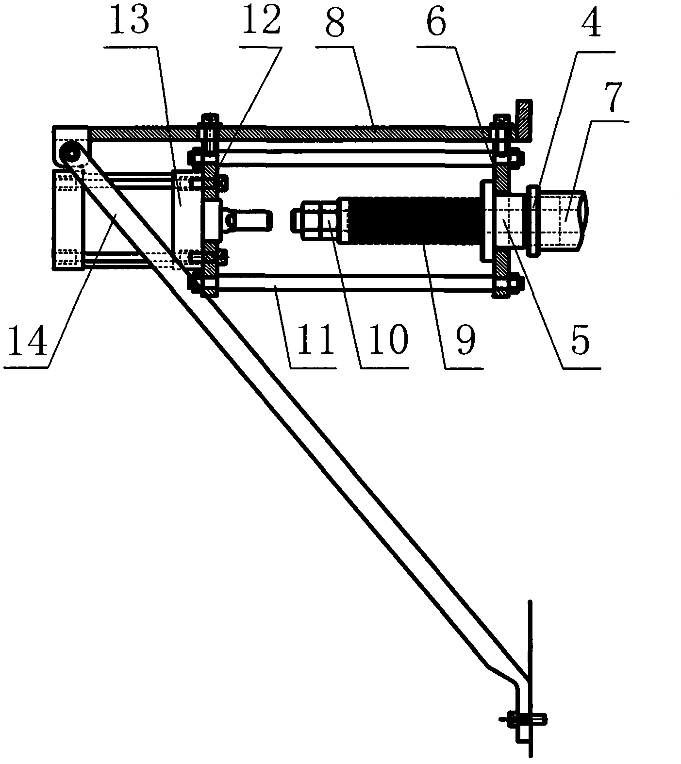
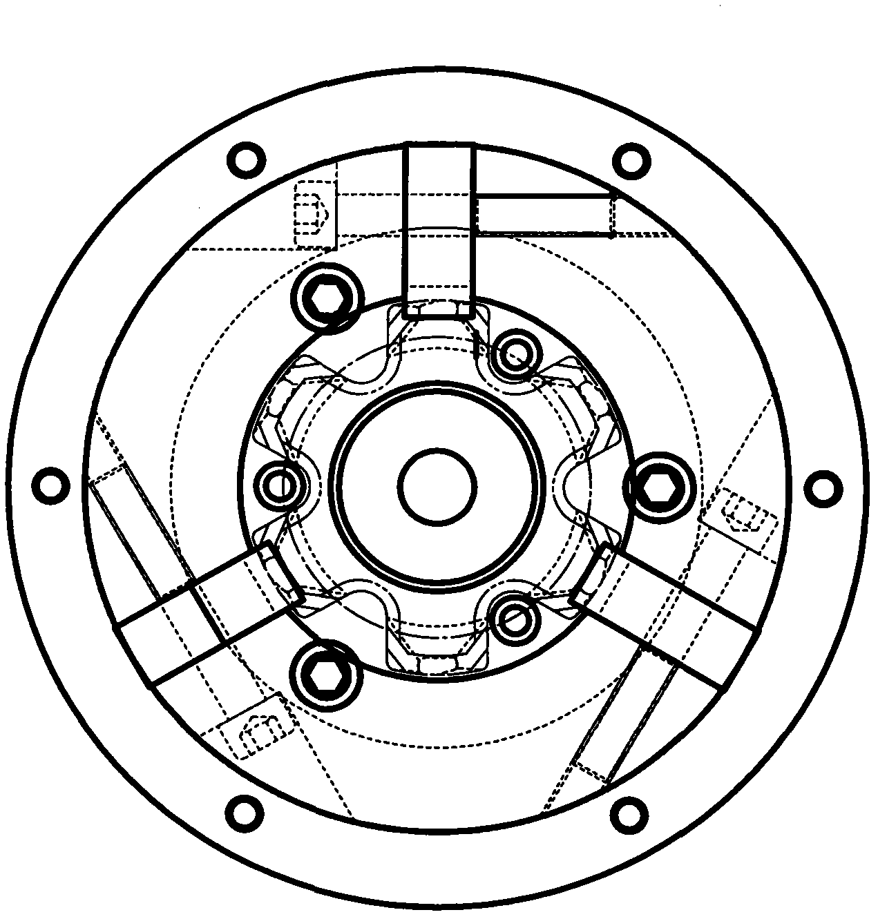
[0015] The pneumatic fixture for claw pole outer flat processing is composed of a pneumatic device 2 and a self-balancing three-jaw chuck 3. The jaw chuck 3 is connected by the pull rod 7 installed in the main shaft of the CNC lathe 1 to complete the processing action.

[0016] The pneumatic device 2 is composed of a locking round nut 4, a coupling head 5, a front pull plate 6, a pull rod 7, a horizontal plate 8, a disc spring 9, an adjusting nut 10, a connecting rod 11, a cylinder connecting plate 12, a cylinder 13 and Horizontal plate support bar 14 forms. The front pull plate 6 is fixed on the spindle of the CNC lathe 1 through the joint head 5 and the locking round nut 4, one end of the cross plate 8 is fixed on the upper part of the front pull plate 6 by screws, and the other end of the cross plate 8 is equipped with a cross plate Support rod 14, the middle part of horizontal plate 8 is fixedly equipped with cylinder connecting plate 12 by screw, and connecting rod 11 is...


PUM


Abstract

The invention relates to a pneumatic clamp for the processing of the claw pole outer surface and belongs to the technical field of claw pole accessories processing. The pneumatic clamp comprises a pneumatic device and a self-balancing three jaw chuck which are coupled with each other through a pull rod; the pneumatic device comrises a coupling head, a front pull plate, a pull rod, a cross plate, a disk spring, a coupling rod, an air cylinder coupling plate and an air cylinder; the self-balancing three jaw chuck comprises a flange plate, a spring pressure plate, a locking tip cone, a locking jaw, a cover plate, a positioning core shaft, and a cylinder. According to the invention, the pneumatic clamp is positioned through the claw pole inner surface, centered through a central hole and clamped through a self-balancing three jaw; operator labor intensity and requirements for operator skills are reduced, and processing efficiency and equipment utilization rate are increased; and the problems as follows are solved: in the prior art that the processing of the claw pole outer surface is carried out through an engine lathe, thus the labor intensity is great, sand holes, air holes and surface accumulated burl of a claw pole blank easily cause a lathe tool to have edge breaking, the tool needs to be polished and adjusted repeatedly, the processing is time-consuming and labor-consuming, and the production efficiency and the product quality are influenced.

Description

Technical field: [0001] The invention relates to a pneumatic clamp for claw pole external flat processing, which belongs to the technical field of claw pole accessory processing for automobiles. Background technique: [0002] The existing method of processing claw poles is to use ordinary lathes for processing, manual clamping, labor-intensive, and because the claw pole blanks are castings, there are defects such as sand holes, pores, and surface buildup, the processing is generally difficult. The turning tool of the lathe is easy to skip the cutting edge. After the cutting, it needs to be re-grinded and adjusted repeatedly. The processing is time-consuming and labor-intensive, which affects the production efficiency and product quality. In addition, the operator is required to sharpen the knife after the turning tool is sharpened, which requires relatively high knife sharpening skills for the operator. The training period for new employees is long and the assessment standar...

Claims


Application Information

Patent Timeline
IPC IPC(8): B23B31/30
Inventor 何守钦徐海霞
Owner 荆州市万寿汽车零部件有限公司
Learn More