
Gate cutting device

A technology of cutting equipment and gates, which is applied in the field of gate cutting equipment, can solve problems such as slow batch shearing speed, difficulty in controlling the shearing size, and inability to cut with nozzle pliers, so as to reduce the risk of defective products and improve work efficiency. High, accurate cutting effect

Inactive Publication Date: 2011-04-13
SHANGHAI FUJITECH PLASTIC
View PDF0 Cites 3 Cited by
  • Summary
  • Abstract
  • Description
  • Claims
  • Application Information

AI Technical Summary

Problems solved by technology

[0003] (1) The cutting size is difficult to control, and there are often problems of cutting more and less;
[0004] (2) Due to manual operation, the batch cutting work speed is slow and the work efficiency is low;
[0005] (3) There is a risk of the product being scratched, and once it is scratched, it may cause defective products;
[0006] (4) For plastic products formed at high temperature, ordinary nozzle pliers cannot cut

Method used


Image

  • Gate cutting device
  • Gate cutting device

Examples


Embodiment

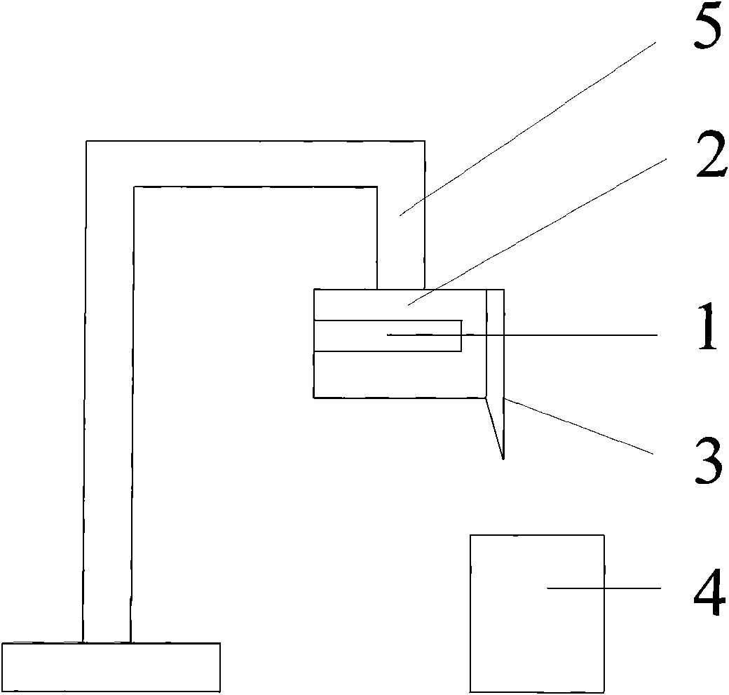
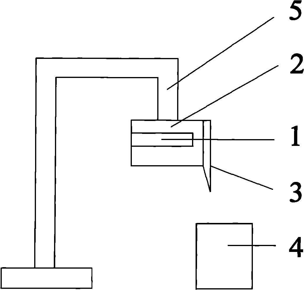
[0021] A gate cutting device, the structure of which is as follows figure 1 As shown, the cutting equipment includes a heater 1, a heat-conducting part 2, a cutting blade 3, a product fixing seat 4 and a punch 5. The heater 1 is connected to the heat-conducting part 2, and the heat-conducting part 2 can be heated by the heater 1, and the heat-conducting part 2 The heat emitted by the heater can be transmitted. The cutting blade 3 is arranged at one end of the heat conducting part 2. The cutting blade 3 can also be heated by the heater 1. The product fixing seat 4 is arranged under the heat conducting part 2. The product fixing seat 4 The cut injection molding product and nozzle are installed and placed on the top, and the punch 5 is connected to the upper part of the heat-conducting part 2, and the punch 5 has a punching effect. When using this device, take the following steps:

[0022] (1) Fix the cutting blade 3 on the heat conducting part 2 with screws;

[0023] (2) Heate...


PUM


Abstract

The invention relates to a gate cutting device, which comprises a heater, a heat conducting part, a cutting blade, a product fixing seat and a punch. The heater is connected to the heat conducting part, the cutting blade is arranged at one end of the heat conducting part, the product fixing seat is arranged below the heat conducting part and the punch is connected to the upper part of the heat conducting part. Compared with the prior art, the invention has the advantages of accurate positioning, capability of controlling cutting size, greater batch cutting speed, nearly no scratching risk in use, high work efficiency, reduced defective products and wide scope of application.

Description

technical field [0001] The invention relates to a cutting device, in particular to a gate cutting device. Background technique [0002] At present, the injection molding of a plastic product generally must be completed through a mold, and in most injection molds, the gate is an indispensable part of the injection filling process. Due to its own limitations, the gates of some injection molding products cannot be cut directly during the injection molding process, and must be removed after the injection molding is completed. Therefore, for this type of injection molding products, the gate removal becomes a complete process. Necessary process for injection molding products. At present, for the removal of this type of gate, the general manufacturers basically use the manual shearing method. The so-called manual shearing method refers to directly cutting the gate by manual water nozzle pliers. However, the manual shearing method has many disadvantages, mainly as follows: [00...

Claims


Application Information

Patent Timeline
Patent Type & Authority Applications(China)
IPC IPC(8): B29C45/38B26D1/08B26D7/10
Inventor 郑德明
Owner SHANGHAI FUJITECH PLASTIC
Learn More