A fully automatic shearing machine

A shearing machine, fully automatic technology, applied in the field of steel plate processing, can solve problems such as costing a lot of man-hours

Active Publication Date: 2017-01-04
ANHUI NINGGUO DONGBO FASTENER
View PDF8 Cites 3 Cited by
  • Summary
  • Abstract
  • Description
  • Claims
  • Application Information

AI Technical Summary

Problems solved by technology

[0002] The processing of steel plates in the prior art usually adopts the method of cutting the coiled steel strip into steel plates according to the required size, however, this requires a lot of man-hours

Method used


Image

  • A fully automatic shearing machine

Examples


Embodiment Construction

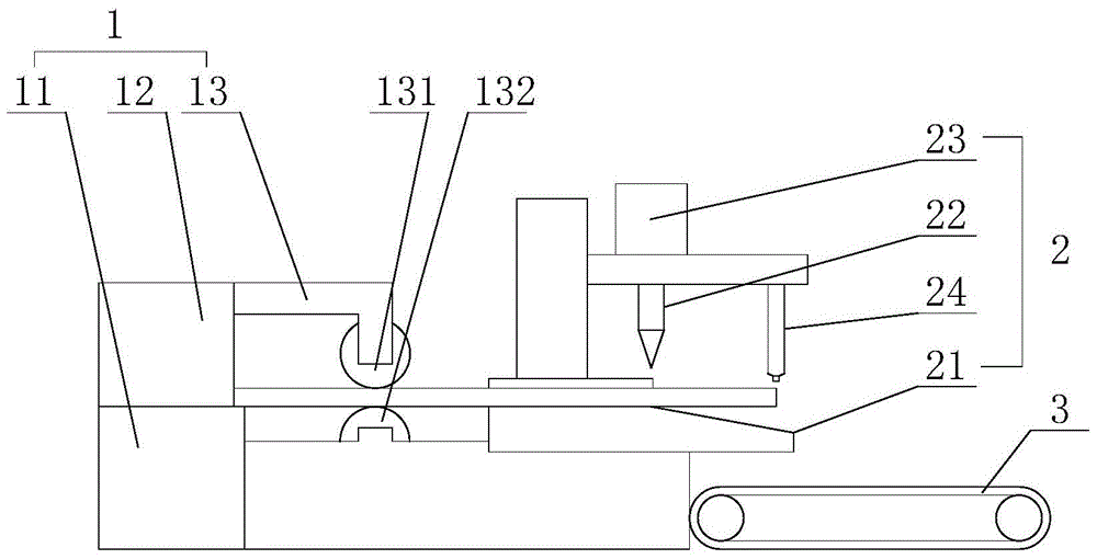
[0016] Such as figure 1 as shown, figure 1 It is a structural schematic diagram of a fully automatic shearing machine proposed by the present invention.

[0017] refer to figure 1 , a kind of fully automatic plate shearing machine that the present invention proposes, comprises: feeding device 1, shearing device 2, discharge conveyor belt 3;

[0018] The feeding device 1 comprises a raw material rack 11, a first drive mechanism 12, and a limit mechanism 13. The first drive mechanism 12 is used to drive the raw material rack 11 to feed, and the limit mechanism 13 is used to limit the position of the steel strip during the feeding process. Mechanism 13 includes an upper roller 131 and a lower roller 132, the distance between the upper roller 131 and the upper roller 132 is consistent with the thickness of the steel plate to be processed, the surface of the upper roller 131 and the lower roller 132 is provided with rubber material, and the upper roller 131 and the lower roller 1...


PUM


Abstract

The invention discloses a fully automatic plate shearing machine, which comprises a feeding device, a shearing device, and a discharge conveyor belt. The feeding device is provided with a limit mechanism, and the shearing device is provided with a proximity switch for controlling the operation of the shearing mechanism. A discharge conveyor belt is arranged below the discharge end of the shearing device. The automatic shearing machine proposed by the present invention can realize automatic feeding of steel strips, automatic cutting according to a predetermined size, automatic output of steel plates, small dimensional error of finished steel plates, and high pass rate.

Description

technical field [0001] The invention relates to the field of steel plate processing, in particular to a fully automatic plate shearing machine. Background technique [0002] The processing of steel plates in the prior art usually adopts cutting the coiled steel strip into steel plates according to the required size, however, this requires a lot of man-hours. At the same time, due to the high weight and rigidity of the steel itself, the length of the steel plate is prone to large dimensional errors. To reduce the dimensional error, it is necessary to carry out post-processing of the steel plate. [0003] Therefore, there is a need for a plate shearing device that can automatically shear the coiled steel strip into plates according to the required length, and the finished steel plate after shearing has small dimensional error and low reject rate. Contents of the invention [0004] In order to solve the technical problems existing in the background technology, the present in...

Claims


Application Information

Patent Timeline
Patent Type & Authority Patents(China)
IPC IPC(8): B23D15/06
Inventor 熊大京曹开林汪金良戴婧
Owner ANHUI NINGGUO DONGBO FASTENER
Why Eureka
Try Eureka