
Plate sawing equipment

A technology for sawing and plate cutting, applied in the field of plate sawing equipment, can solve the problems of sawing size error and cutting precision reduction, etc., and achieve the effects of accurate cutting saw size, improved sawing precision, and improved sawing production efficiency

Pending Publication Date: 2019-11-26
南通思威机械有限公司
View PDF0 Cites 2 Cited by
  • Summary
  • Abstract
  • Description
  • Claims
  • Application Information

AI Technical Summary

Problems solved by technology

[0003] The purpose of the present invention is to provide a plate sawing equipment to solve the technical problems that the cutting accuracy is reduced when cutting a large number of plate parts in the prior art; and there is an error in the sawing size

Method used


Image

  • Plate sawing equipment
  • Plate sawing equipment

Examples


Embodiment Construction

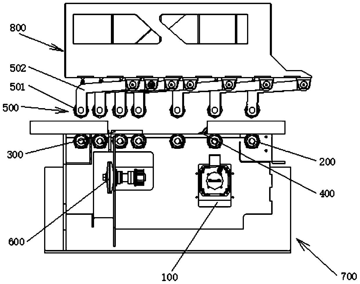
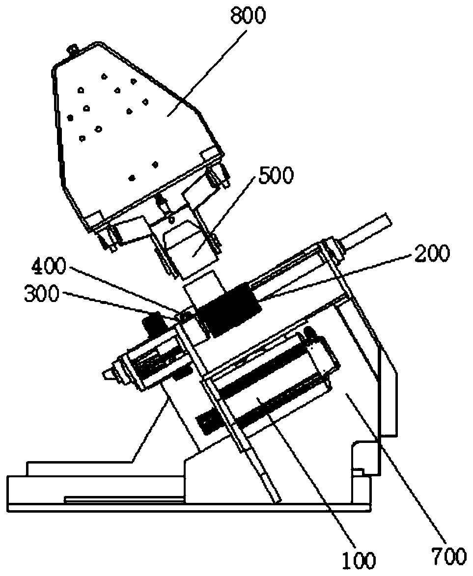
[0032] discussed below Figure 1 to Figure 2 , and the various embodiments used to describe the principles of the invention in this patent document are by way of illustration only and should not be construed as limiting the scope of the invention in any way. Those skilled in the art will appreciate that the principles of the present invention may be implemented in any suitable type of lumber sawing apparatus. The terminology used to describe various embodiments is exemplary. It should be understood that these are provided only to aid in the understanding of the description and that their use and definitions do not limit the scope of the invention in any way. The terms first, second, etc. are used to distinguish objects with the same set of terms and are not intended to imply temporal order in any way unless expressly stated otherwise. A group is defined as a non-empty group containing at least one element.

[0033] In order to make the purpose, technical solutions and advan...


PUM

PropertyMeasurementUnit
thicknessaaaaaaaaaa
widthaaaaaaaaaa
lengthaaaaaaaaaa

Abstract

The invention relates to plate sawing equipment. The plate sawing equipment is characterized by comprising an upper body (800) and a lower body (700), wherein the upper body (800) is used for pressingand positioning a first surface of a to-be-sawn plate, and the lower body (700) is used for detecting and conveying the to-be-sawn plate and conduct cutting treatment on the to-be-sawn board; the upper body (800) comprises an upper compression roller (500) and a supporting upper machine body, wherein the upper compression roller (500) is positioned at the bottom of the supporting upper machine body, and is connected with the supporting upper machine body into a whole; and the upper compression roller (500) of the upper body (800) can move to get close to or get away from the lower body (700).

Description

technical field [0001] The invention belongs to the technical field of sawing, and in particular relates to a plate sawing device. Background technique [0002] In the prior art board sawing equipment, the board parts that need to be sawed and the backing board are located in a horizontal position. When the board parts need to be sawed, the bottom surface of the board parts is usually supported by the lower idler roller, and the Plate parts, at the same time, the upper pressure roller presses the surface of the plate parts to realize the transfer, and at the same time, one side of the plate parts is attached to the backing plate. During the sawing process, because the plate parts and the backing plate are in a horizontal position, it is inevitable that the plate parts The side of the part is separated from the backing plate, so that the cutting of plate parts lacks a positioning reference, thereby reducing the cutting accuracy. Especially when it is necessary to cut a large...

Claims


Application Information

Patent Timeline
Patent Type & Authority Applications(China)
IPC IPC(8): B23D45/00B23D47/04
CPCB23D45/00B23D47/04
Inventor 沙玉勇
Owner 南通思威机械有限公司
Learn More