
Manufacturing method of multilayer shell-core composite structural part

A composite structure and multi-layer shell technology, which is applied in the direction of chemical instruments and methods, layered products, ceramic layered products, etc., can solve the problem of inability to obtain multi-layer shell-core composite structure parts, inability to organize, precise control of performance, and mechanical bearing Good capacity and other issues, to achieve the effect of good lasting stability, strong impact load capacity, and strong mechanical bearing capacity

Active Publication Date: 2011-04-13
SUZHOU DINGAN ELECTRONICS TECH
View PDF3 Cites 64 Cited by
  • Summary
  • Abstract
  • Description
  • Claims
  • Application Information

AI Technical Summary

Problems solved by technology

However, the above-mentioned various forming techniques cannot be used to make multi-layer shell-core composite structural parts with special shapes, or cannot obtain multi-layer shell-core composite structural parts with large and uniform layer thickness, or cannot adjust the thickness of each layer and the multi-layer shell core. The microstructure and performance of core composite structural parts are precisely controlled, but it is difficult to be applied to the manufacture of multilayer shell-core composite structural parts involved in the present invention, that is, the application of the prior art has high surface hardness, wear resistance, corrosion resistance and It is difficult to obtain multi-layer shell-core composite structural parts with good thermal properties, high bonding strength between shell and core, good mechanical bearing capacity, high impact toughness, high performance durability and stability.

Method used


Image

  • Manufacturing method of multilayer shell-core composite structural part
  • Manufacturing method of multilayer shell-core composite structural part
  • Manufacturing method of multilayer shell-core composite structural part

Examples


Embodiment 1

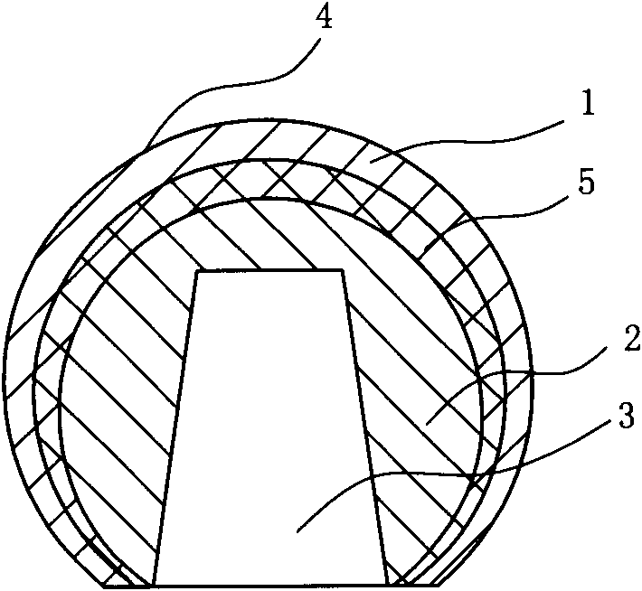
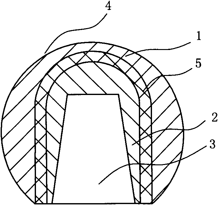
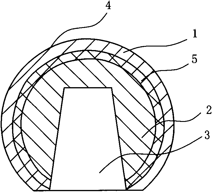
[0038] A femoral head with a multilayer shell-core composite structure, which is composed of a high-purity ultrafine alumina ceramic spherical shell layer 1, an alumina-based (niobium) cermet middle layer 5 (i.e. transition layer) and a niobium metal inner core 2. The composite structure of multilayer tissue has such Figure 1 to Figure 5 The five forms shown can be selected according to the application requirements.

[0039] see Image 6 , the specific preparation process is:

[0040] (1) Prepare high-purity ultrafine alumina powder, alumina-based (niobium) cermet composite powder and niobium metal powder injection molding feedstock respectively. The purity of the high-purity ultrafine aluminum oxide powder is greater than 99.9 wt%, and the particle size is 0.5-10 μm; the purity of the niobium metal powder is greater than 99.8 wt%, and the particle size is 0.5-10 μm. In order to reduce the sintering temperature and improve the sintering performance, 0.25wt.% MgO powder is a...

Embodiment 2

[0048] A multi-layer shell-core composite structure femoral head, which is made of high-purity ultra-fine alumina ceramic spherical shell layer 1, ZrO 2 (3Y 2 o 3 )-80wt.%Al 2 o 3 Toughened ceramic interlayer 5 and ZrO 2 (3Y 2 o 3 )-20wt.%Al 2 o 3 Toughened ceramic core 2 consists of three parts.

[0049] see Image 6 , the specific preparation process is:

[0050] (1) Prepare high-purity ultra-fine alumina powder, ZrO 2 (3Y 2 o 3 )-80wt.%Al 2 o 3 Composite powder and ZrO 2 (3Y 2 o 3 )-20wt.%Al 2 o 3 Composite powder injection molding feed. The purity of high-purity ultra-fine alumina powder is greater than 99.9wt%, and the particle size is 0.5-10 μm; ZrO 2 The purity of the powder is greater than 99.8 wt%, and the particle size is 0.5-10 μm. In order to reduce the sintering temperature and improve the sintering performance, 0.25wt.% MgO powder is added to the high-purity ultrafine alumina powder as a sintering aid. Prepared modified alumina powder, ZrO ...

Embodiment 3

[0058] A femoral condyle prosthesis (one of artificial knee joint components) with a multi-layer shell-core composite structure, consisting of Ti6Al4V core layer 1, Ti6Al4V-20vol.%Al 2 o 3 Transition layer 2, Ti6Al4V-60vol.%Al 2 o 3 Transition layer 3 and high-purity ultra-fine Al 2 o 3 The ceramic shell layer 4 is composed.

[0059] see Image 6 , the specific preparation process is:

[0060] (1) Separately prepare high-purity ultra-fine Al 2 o 3 Powder, Ti6Al4V-60vol.%Al 2 o 3 Composite powder, Ti6Al4V-20vol.%Al 2 o 3 Composite powder and Ti6Al4V powder injection molding feedstock. High-purity ultra-fine Al 2 o 3 The purity of the powder is greater than 99.9wt%, and the particle size is 0.5-5μm; the purity of the Ti6Al4V powder is greater than 99.5wt%, and the particle size is 10-35μm. In order to reduce the sintering temperature and improve the sintering performance in high-purity ultra-fine Al 2 o 3 Add 0.1wt.% MgO powder to the powder as a sintering aid. ...


PUM

PropertyMeasurementUnit
thicknessaaaaaaaaaa
thicknessaaaaaaaaaa
thicknessaaaaaaaaaa

Abstract

The invention discloses a manufacturing method of a multilayer shell-core composite structural part, which comprises the following steps of: (1) respectively preparing feed for injection forming of a core layer, a transition layer and a shell layer, wherein powder in the feed of the core layer and the powder in the feed of the shell layer are selected from one or a mixture of some of metal powder, ceramic powder, or toughened ceramic powder and are different from each other, and the powder in the feed of the transition layer is gradient composite powder; (2) respectively manufacturing blanks of the multilayer shell-core composite structural part layer by layer with a powder injection forming method; (3) degreasing the blanks; and (4) sintering the blanks to obtain the multilayer shell-core composite structural part. The multilayer shell-core composite structural part is manufactured with the powder injection forming method, and has the advantages of high surface hardness, abrasion resistance, uniform thickness of the shell layer, stable and persistent performance, strong binding force between the shell layer and the core layer due to the transition layer, good integral bending strength and good impact toughness and is difficult to crack.

Description

technical field [0001] The invention relates to the preparation of a multilayer shell-core structural part, in particular to the preparation of spherical, hemispherical, hemispherical shell, columnar, cylindrical or special-shaped multilayer shell-core composite structural parts. Background technique [0002] Spherical, hemispherical, hemispherical shell, cylindrical or cylindrical parts and other special-shaped parts are widely used in various fields, among which, in many applications, parts are required to have good wear resistance, corrosion resistance and heat resistance on the one hand. And extremely high dimensional matching accuracy and smoothness, on the other hand, it has high strength, toughness, high mechanical bearing capacity and machinability. Common such parts include, for example, a spherical artificial femoral head, a hemispherical shell-shaped artificial acetabulum, a cylindrical plunger, a cylindrical ball valve body, and a shaped femoral condyle prosthesi...

Claims


Application Information

Patent Timeline
Patent Type & Authority Applications(China)
IPC IPC(8): B22F3/00B22F3/10
CPCB22F3/105B22F7/02B22F3/225B22F7/06B22F3/1021B32B18/00C04B35/111C04B35/119C04B35/4885C04B35/634C04B35/638C04B35/6455C04B2235/3225C04B2235/3229C04B2235/6022C04B2235/77C04B2235/96C04B2237/343C04B2237/348C04B2237/58C04B2237/84A61F2/34A61F2/32B22F3/12B22F3/15B22F7/008C04B35/64A61F2/3601
Inventor 李亚东李亚军
Owner SUZHOU DINGAN ELECTRONICS TECH
Learn More